Photo Gallery Page 3
| Pg. 1 | Pg. 2 | Pg. 3 | Pg. 4 | Pg. 5 |
Vintage Hi-Fi Revamps
| Warning: If extensive modifications to classic hi-fi gear offends your collector's sensibilities, bypass this page! |
| I've been working with tube hi-fi gear since it was "state of the art", usually as a hobbyist but with the occasional stint at stereo repair shops. I've only recently started documenting the projects that come my way, here you'll find a couple of the more recent ones. (Now if I can only get into the habit of taking "before" pictures!) |
HK Dignity Reclaimed
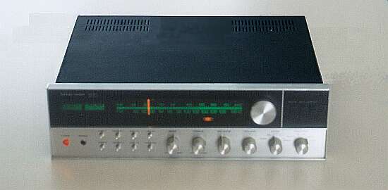
Nice looking Harmon Kardon 930 receiver, wouldn't you say? Pity that it's solid state... almost an insult to the HK legacy. Well, let's see what we can do about that! |
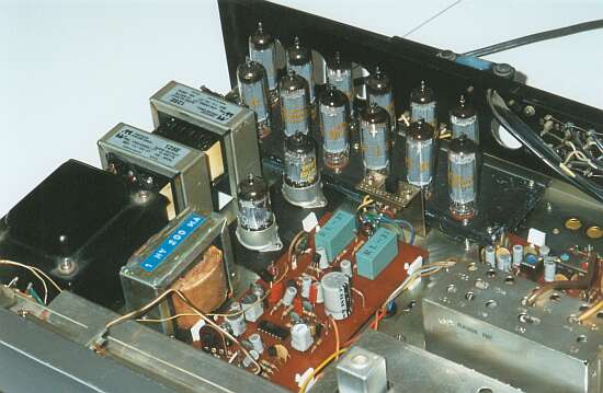
... and here it is with the cover off. The transistor heat sinks are replaced by a bay of 12 35C5's, and a pair of 12AU7's live where the filter caps used to be. A pair of Hammond 125E's snuggle cozily where the second power transformer used to be, and there's even room left over for a 1-henry filter choke. |
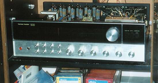
This is where it lives now, in the cabinet next to my computer. This is the best I've ever heard my Yamaha sound card... except for the times I run it through my RA-100! The tone-control preamp is still solid state. Maybe one day I'll revisit that also! |
| TECHNICAL DETAILS: The full schematic diagram is now provided for your convenience (as of Jan. 2003). The 35C5's operate in push-pull parallel, 3 valves per section. Filaments of the 35C5's line operated. B+ voltage 200V (derived mostly from the unused primary winding reserved for 240v operation), cathode current 20 mA per valve (240 mA quiescent total). Class AB1 operation, output power about 10 watts per channel (less than the 15 watts that might be expected because of relatively high load resistance, chosen to minimize distortion). Grid bias partly obtained from a fixed supply, and partially from individual unbypassed cathode bias resistors, which also apply some local negative feedback. The conventional 12AX7 preamp stages are followed by 12AU7 cathodyne phase splitters, optimised for linearity since a high output swing is not needed. Mild NFB (about 6 dB) applied from speaker outputs to cathodes of preamp stages. 3dB points at 80 Hz. and 22000 Hz. Flat within 1/2 dB from 120 Hz. to about 18 kHz. Subjective assessment: it's certainly not a Citation, but still sounds great! |
|
... and Marantz's too!
November, 2002
|
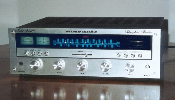
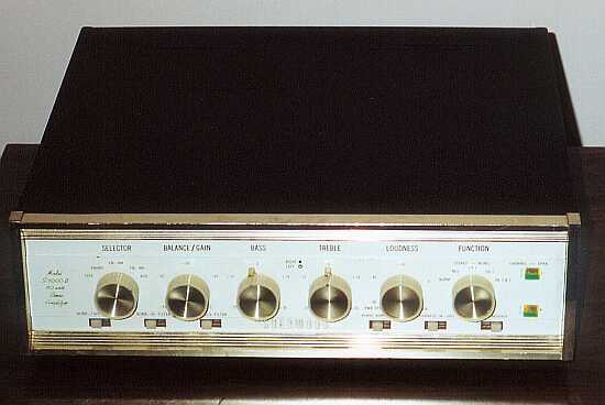
| Another beautiful receiver, this time by Marantz, originally known for its top-notch tube hi-fi designs. Unfortunately, this one was a later, all-solid-state receiver manufactured in Japan. This poor thing was a castaway, dirty and broken when it came my way. Now it again holds a place of honour as my lovely wife's computer "multimedia" amplifier. |
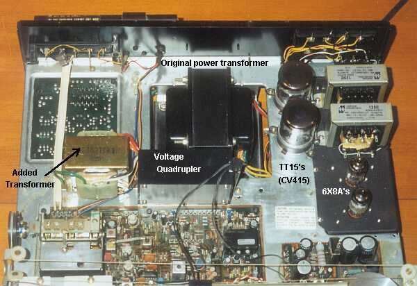
| Here's what it now looks like under the hood. The black sub-chassis fills the hole where the transistor heat-sinks used to be. The project box houses the voltage quadrupler, which allows the original power transformer to supply the B+ for the tubes. Another added transformer (salvaged from a low-end boom-box stereo) helps take the heat off the main unit. |
|
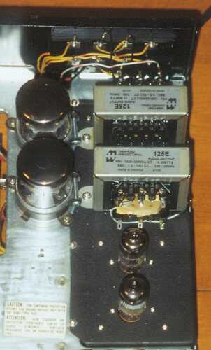
Close-up of the tube subassembly. The holes for the original filter caps are now populated by a pair of TT15 (CV415) dual beam tubes, for over 10 watts per channel of crystal-clean tube sound. These sturdy little valves were once used for military-grade mobile VHF transmitters. Sockets for these are rare and expensive, so I opted for a clamp-support mounting method, combined with gold-plated DB connector pins for the contacts. In front of the Hammond 125E output transformers are the two 6X8A's, a triode/ pentode combination originally intended for television tuners. A rather novel (if I say so myself) phase splitter arrangement allows the use of this tube even with its shared cathode. |
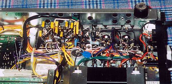
| And this is the under-side of the chassis. The tidy point-to-point wiring around the new tube section provides a nice counterpoint to the phenolic PC boards everywhere else in the system. |
| TECHNICAL DETAILS: The circuit details for this one are interesting enough to warrant a more complete treatment than the other units shown on this page. See the page on Experiments with Paraphase Splitters for schematics and performance reports. |
Sherwood S5000-II Redo
This poor old Sherwood was in pretty rough shape when I got it. The 7591's bases were baked to a a deep crisp, main filter caps blown up leaking corrosive goo... not a pretty sight. Thankfully the other cans were fine, and easily re-formed to over their rated capacitance. Lots of elbow grease and tinkering, and it once again looks spiffilicious. |
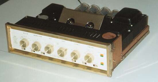
Take the cover off, if you didn't know better you'd think it was "factory". But if you know this amp, you'll immediately exclaim, "Those aren't 7591's!" Indeed. They're Reflektor 6L6GC's, quite similar to the venerable 6L6GB's of yore, mounted on a completely redone mounting bracket. (A set of metal JAN 6L6's would be an interesting option also.) |
|
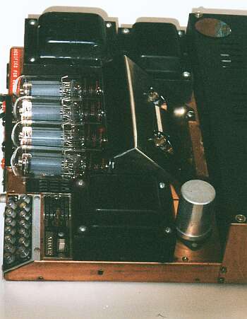
Side view of the new output tube layout. The angled mount was cut away, and replaced with a screen for improved ventilation. The old heat shround (a.k.a. "base baker") was moved back to cover the wiring on the new bracket; the original design had raw B+ on the top side! (shudder...). Oval holes added in the relocated shroud let the preamp/ phase splitters poke their cute little pointy heads out. Upper right: where the insulated voltage doubler can lived is now the access hole for overall grid bias. |
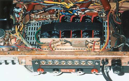
Underneath the vent screen there's now plenty of room for a capacitor board to replace the input voltage doubler caps, and the first two filter sections; since this is a demanding service (witness the blown-out originals), series-parallel combinations of caps give a conservative rating and hopefully long running life. |
|
TECHNICAL DETAILS: The use of lower Gm output tubes required a new bias supply, consisting
of a separate voltage doubler on the same transformer winding that supplies the original DC
filament/ bias supply. This affords up to 60 volts, in practise this is adjusted to about 55 volts
using an overall bias voltage control accessible through the hole in the preamp cover. Another
balance pot was added for left-right channel bias; the unit already had balance pots for push-pull
on each channel.
The driver preamps and cathodyne phase splitters also required optimisation, a separate filter network off the first filter section increases its B+ to about 430 volts; previously it was connected to the same filter section as the output screens, resulting in considerable sag at higher power. Also, the grid biasing method was changed to a 4:1 voltage divider for maximum output swing. The plate and cathode resistors were also decreased to 33k to give better drive and output balance. The result is about 10 volts of headroom above the full-power drive required by the 6L6GC's (about 200V P-P). Thankfully, there is plenty of preamplifier gain to easily accomodate the reduced output stage sensitivity. Output power is a solid 32 watts per channel; the unit was originally rated at 40 watts, but looking at the size of the iron I'd take that rating with a grain of salt. 10 ohm resistors in each output tube cathode allow for precise measurement of cathode current, and the combination of bias and balance pots allows exact calibration. Add plenty of DeOxit, elbow grease, and TLC, and it's once again a terrific- sounding (and -looking) amplifier! |
 |
 |
 |
BACK | HOME | NEXT |
Or jump to:
| Pg. 1 | Pg. 2 | Pg. 3 | Pg. 4 | Pg. 5 |
Tube site Home
Enough of this, take me to Fred's artsy side!