MINIBLOK II: A PUSH-PULL TRIODE AMPLIFIER
by Fred Nachbaur, Dogstar Music ©2002
4: CONSTRUCTION AND TESTING
I went to pains to design this project around parts that are readily available. The
parts list offers suggested sources for most of the parts. The
only one that might be a challenge to find at low cost is the output transformer. I used
a vintage transformer from my "treasure chest", with a tapped secondary allowing
experimentation with either a 42:1 or 28:1 turns ratio. A reasonable substitute would be the
model TF107 or TF110 transformers (both 28:1) on the
Other Transformers page at
Triode Electronics. However, for the price you'd
probably be better off with one of the Model 125's from
Hammond. While the smaller
125A or 125B devices would be adequate, the larger ones would give better bass
response, culminating in the 125E.
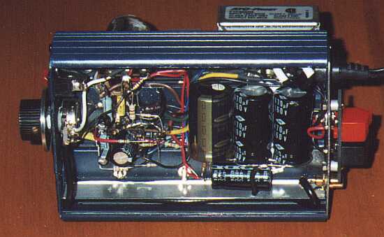
Construction of the MiniBlok SET Amplifier is relatively straightforward and non-critical, as
electronics projects go. You could take any number of approaches to the mechanical layout; as
you can tell from the pictures, I duplicated the "recycled" look of MiniBlok I by
housing the prototype in a blue-anodized extruded aluminum case that used to be a small DC-AC
inverter. There are a few more ideas in the original
MiniBlok article.
As before, this article assumes that you're reasonably skilled at soldering, since this is
an ability that is best learned by doing (preferably with the assistance of a coach).
Be careful about wiring, especially in the comparatively high-voltage plate
circuits. If you're unsure about how the tube connections are numbered, click
here (use your browser's Back button to return to this page
afterwards.) Be sure to use capacitors rated at the specified (or higher) voltage
rating. I suggest staying away from "carbon composition" type resistors, especially
for R2 and R12; otherwise you can get another classic tube sound - lots of hiss. That being
said, if you want to use carbon-comp resistors for authenticity's sake, try to find the later
Allen-Bradley ones; these will have a smooth finish and sharp, square edges (as opposed to the
older and cheaper ones with rather rounded corners and a dull look; these can be awful as
regards tolerance and noise).
A word about grounding: The ground symbols (three horizontal lines suggesting a downward-pointing
arrow) indicate a connection to a common grounding point, which is in turn the only connection
to the chassis (if using a metal chassis). This common point should normally be the ground end of
the input jack. Since this is a relatively low-gain system, grounding isn't especially critical;
so you could cheat and use, for instance, the ground lugs on your tube socket (if available) for
tying components such as R3, R15, R16, C8, C11 and C12, and V1 socket pin 7 to chassis ground.
The important thing is to avoid voltage drops caused by the high inrush current into the B+
filter caps (C1 - C3) from getting into your audio; therefore be sure that D2, C2 and C3 are
connected together, with a wire connected to their common point at one end, and to the common
ground point at the other.
Some more comments on the power supply: The MiniBlok II uses two separate power transformers;
unlike the previous project, however, I strongly recommend that you use "Class 2"
transformers (also referred to as "bell transformers") of the type used in house
wiring. The reason is that the higher current requirement makes the cheaper experimenter /
replacement transformers less than ideal. You can often find Class 2 transformers at surplus
or second-hand stores if you poke around a bit. If you can't find any at a decent price,
you should be able to use the more ordinary run of transformers rated for at least 2 amperes
at 24 volts. Note when wiring up the power supply that transformer T2 (the high-voltage
step-up transformer) is wired backwards; what used to be its primary is actually our
secondary winding.
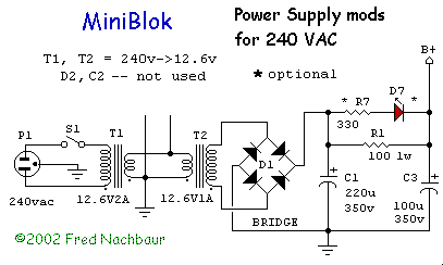
Modifications for 240 volt supply:
It is entirely possible to build a MiniBlok for use with 240 VAC, 50- or 60- Hz. power.
Transformers T1 and T2 will be 240V to 24V transformers, rated for at least 2 Amperes.
However, since the output of T2 will be on the order of 220 volts already,
the voltage doubler for the B+ supply is un-necessary. Diodes D1 and D2 are therefore
replaced by a 1A, 600 volt (or higher) "full-wave bridge" module (or four
discrete diodes, if you prefer). Capacitors C1 and C2 are replaced by a single 220
µF, 350V unit. Other than that, everything else remains the same.
Wiring and Testing
I recommend testing (and debugging, if necessary) the power supply first. Be very careful about
diode and capacitor polarities! The diodes have a band at the cathode end (this is the end that
corresponds to the "bar" in the schematic symbol). The capacitors will usually be marked
at the negative end with a bar or line consisting of a row of "-" symbols. At the
low-voltage filament supply output on opposing tube sockets' pins 7 and 8 (no load) you'll
typically read about 25-26 volts AC. At the bias output you should read about -15 volts. At the
high-voltage output you'll read about 300-320 volts under no-load conditions. Be careful about
accidental shorts; these can make the Magic Smoke come out of your transformers or other components,
and render them useless. If you chose to install the optional LEDs, you should see the green LED (D5)
light up when power is on. The red one (D7) should only flash briefly while the capacitors
charge, then extinguish.
IMPORTANT:
The high-voltage filter capacitors will hold a charge for a long time after
power-off, with no tube installed. To avoid an unpleasant surprise as you're working on this or
any tube circuit, discharge the high voltage capacitors after turning off the unit and
unplugging it from the wall socket. The best way to do this is to clip-lead a 10K resistor between
the positive and negative terminals of the power supply (the terminals of C3 in this case), and
leave it on for at least 30 seconds before proceeding with your work. (Don't forget to unclip it
before applying power again!)
Wire up the rest of the circuit. Be careful that every connection is correct as you're making it.
This version is significantly more complex than the single-ended design, so care in wiring is
even more important. Don't even think about plugging the tubes into their sockets just yet,
though!
Do the following final tests:
- With the unit not plugged into the wall outlet, and after being sure the filter
capacitors are discharged, connect the negative lead of your ohm-meter to common ground, and
make the following measurements to pins on the indicated tube socket(s):
- Pin 7 (V1): zero ohms
- Pin 8 (V2): very near to zero ohms (may read zero on your meter)
- Pin 7 (V2), pin 8 (V1): infinite
- Pin 3 (both): about 330 ohms
- Pin 6 (both): about 820 ohms
- Pin 4 (V1): zero to 100k, as volume control turned from zero to maximum.
- Pin 4 (V2): about 470k.
- Pin 1 (both): about 470k.
- Switch your meter from ohms to the highest DC voltage range (leave the negative lead connected
to the common ground point), plug in the amplifier, and turn it on. Note that the tubes are not
yet plugged into their sockets. Make the following voltage readings:
- Pin 1 (both): about -15 volts (may show a bit lower on voltmeters with low
input resistance)
- Pin 2 (both): about 300 - 320 volts
- Pin 3 (both): zero volts
- Pin 4 (V1): zero volts
- Pin 4 (V2): -15 volts volts
- Pin 5 (both): about 300 - 320 volts
- Pin 6 (V1): zero volts
- Pin 6 (V2): -15 volts
- Switch your meter to a 20 volt or higher AC voltage range (leave the negative lead connected
to the common ground point). Make the following voltage readings:
- Pin 7 (both): zero volts
- Pin 8 (V1): zero volts
- Pin 8 (V2): about 26 volts
- Turn off the amp, and plug in the tube. Connect a 4 to 10 ohm dummy load resistor to the
speaker terminals. Leave your meter in the 20 volt or higher AC voltage range (leave the
negative lead connected to the common ground point). Turn on the amp and take the following
voltage readings:
- Pin 7 (V1): zero volts
- Pin 8 (V1): about 12 volts
- Pin 7 (V2): about 12 volts
- Pin 8 (V2): about 24 volts
- Switch your meter back to the highest DC voltage range (leave the negative
lead connected to the common ground point), and take the following voltage readings:
- Pin 1 (both): about -15 volts (may read lower on analog meters with low
input resistance)
- Pin 2 (both): about 200 - 220 volts
- Pin 3 (both): about 12 volts
- Pin 4 (V1): zero volts
- Pin 4 (V2): near zero volts (-3v to +3v)
- Pin 5 (both): about 130 - 150 volts
- Pin 6 (V1): about 1.5 volts (you may have to switch to a lower range)
- Pin 6 (V2): about 1.5 volts lower (more negative) than pin 4 (V2)
Everything ok? Great! Turn the amp off, button it up, disconnect the dummy load resistor and
connect your speaker in its place. Connect your input source, turn on the amp, and enjoy!