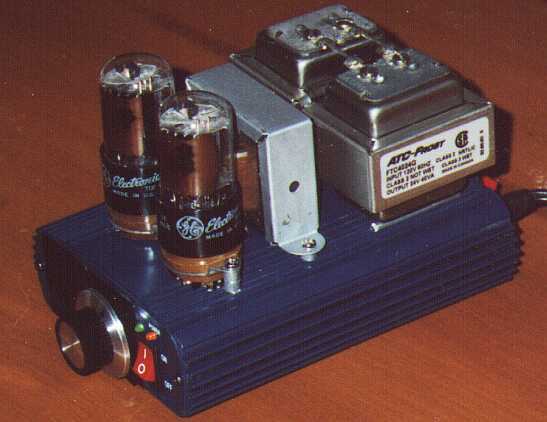
MiniBlok II
A LOW-COST PUSH-PULL TRIODE AMPLIFIER
Published December, 2002. ©2002 by Fred Nachbaur
1: INTRODUCTION
MiniBlok II is a push-pull version of the well-received
"MiniBlok" single-ended
triode amplifier. It sports up to about 3.5 watts of output power (compared to just over
1 watt for the SET version), and makes a great follow-up project if you're interested in
exploring the sonic differences between these two popular (and often opposing) philosophies.
As before, simplicity and low cost were placed high on the design criteria. By necessity,
the parts count and number of connections is higher in the push-pull version, since in a
very real sense a push-pull amp is two single-ended amplifiers yoked together.
This project uses readily available parts, many of which can be scrounged from fairly
well-stocked junk bins. Even if all parts are purchased, it is unlikely that the cost of
parts will exceed $150. The same step-down / step-up power supply scheme is used, except that
this time somewhat higher-quality "Class 2" transformers are used because of the
higher supply requirements. Construction is relatively non-critical, and because of the
relatively low supply voltages used, is even comparatively free of electrocution hazard.
That being said, some prior electronics construction experience is recommended, and personal
safety can never be overstressed.
What's a Push-Pull Amplifier?
Imagine an old-fashioned well pump with a long handle that is used to pump the water. A
single person can thus pump water from the well by pulling the handle down, and pushing it
back up again. This would be comparable to a single-ended amplifier.
Now imagine that a second handle is attached, pointing in the opposite direction. Now two
people can pump at the same time, effectively doubling the amount of power applied to the pump.
While one person is pulling down on his handle, the other person is pushing up on his. The
electronic analogue to this situation is called - appropriately enough - a "push-pull"
amplifier.
Note that the two "signals" are out of "phase" with each other; while
one side is pushing, the other is pulling. This has an added advantage over simply paralleling
two single-ended systems (for example, putting two identical handles on the same side of the
pump). When one person is at the weakest portion of the stroke (for example, the bottom), the
other person will be at the strongest portion of his stroke (the top). This translates, in
electronic terms, to less distortion of the incoming signal, since the two half-waves will
be symmetrical.
The sketch above illustrates one way of accomplishing this push-pull action in an amplifier.
Note that we have what is essentially two separate single-ended amplifiers, each with its
own preamplifier, with their outputs "yoked together" by means of a tapped output
transformer, which feeds the speaker load.
Let's follow the signal through from the input. It will of course be amplified by the
preamplifier stage, as suggested by the sine-wave legends. What's more, it will also be
inverted; in other words, positive voltage peaks become negative, and vice versa. It's
amplified further by the power stage on the left, and inverted once again at the left-side
power amplifier's plate.
For the power amplifier stage on the right side, however, we need a signal at its control
grid that's out of phase with (inverted from) the control grid signal on the left-side stage.
This can be accomplished simply by having another preamplifier stage, which gets its input
from the left power amp control grid. In this case, however, we're not interested in gain; we
therefore "throw away" the unwanted gain in a voltage divider, whose division ratio
is the same as the inverter stage's voltage gain. The net result is that the right-side power
amplifier stage sees the same signal as the left side, except that it's inverted.
This scheme is called the "paraphase splitter". It should be noted that this is
just one way of obtaining the two out-of-phase signals required for push-pull output stages.
It's also not particularly the best way; since the inverted-side signal has to pass through
an extra tube stage, the symmetry (and therefore even-order harmonic suppression) is not as
good as some other approaches, notably the "cathodyne" and "long-tail pair"
phase-splitting schemes. However, the basic paraphase has its own advantages, covered in more
detail in the
next (How It Works) section.
Why go to the trouble?
We've already touched on one of the advantages to using a push-pull topology; reduction of
even-order harmonics because of the inherent symmetry of the design. However, there are other
advantages also; most obviously, higher output power.
On the surface it would seem that one would get exactly twice the possible output power
compared to a single-ended amplifier, all other things being equal. In practise, however, we
can do even better than that. For example, the push-pull version of the MiniBlok easily pushes
3 watts, compared to the single-ended version's one watt. There are two main factors at work:
- Because of the way that power is supplied to the output transformer's center tap, there
is little or no DC magnetization taking place in the transformer core. This is because the
DC currents in the two halves are equal-but-opposite, effectively cancelling. The output
transformer therefore doesn't need an air-gap to prevent core saturation, making it more
efficient.
- Because of the push-pull action, the amplifier can be driven harder before clipping. Even
if one of the tubes is briefly "cut off", the other one will be conducting heavily,
thereby "taking up the slack." This is a form of what's called Class AB operation,
in which it is normal for the output tubes to briefly go into non-conduction on large signals.
It should be noted that if this is carried to extremes, such as by biasing the tubes very close
to cutoff to start with, another kind of distortion called "crossover distortion"
comes into play, giving such designs a hard edge. In the MiniBlok II, however, the amplifier
remains in Class A most of the time, except on the highest peaks. Since the conducting side
is already drawing heavy current under these conditions, the effect of the other side dropping
out is greatly minimized.
-
The push-pull topology has a great deal of inherent power-supply hum cancellation. This may
not be a big deal in small amplifiers, where filter caps are relatively small and inexpensive.
For for larger amps, however, it becomes increasingly more appealing to use push-pull in
order to reduce the power supply filter capacitor requirements.