
3: CONSTRUCTION
As mentioned at the outset, my own version of "G'Zot!" was built around what I had
available. I tried to make use of stuff that otherwise would have either been tossed out, or
continue to languish in some dusty old box. The chassis is a case in point - my wife's PC
power supply had died some months ago, and I couldn't bring myself to toss out that nice
shiny case. So this forms my chassis.
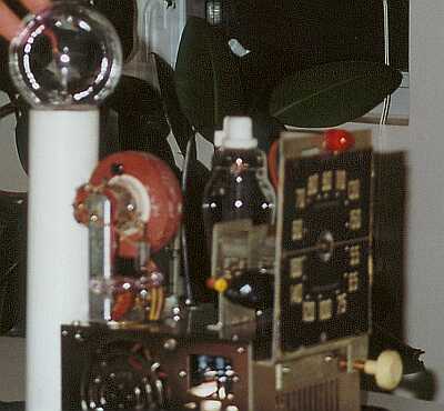
The flyback transformer was a "new old stock" that would have probably been
eventually tossed out also. Hunt around TV shops that have been in business for many years,
you'll very possibly get lucky also. Most of these will have a gazillion taps on them; how do
you figure out which ones to use?
The secondary is usually quite easy. The hot side will be the connection to the anode of the
CRT, and will usually be a large, insulated connector. Use your ohm-meter to find the cold
side, by connecting one lead to the hot terminal, and poking around for the terminal with the
highest resistance. This will typically be on the order of many hundreds of ohms (about 700
ohms in my case). If you find another tap relatively close to the cold end, mark this one also;
it makes a great "tickler" output for a xenon flash tube (discussed later).
How about the primary? You'll probably find that there are several other windings, often even
on other legs of the transformer core. I got the best results by using the other winding
co-linear with the main secondary. The other winding on the opposite leg of the core was
simply tied off to prevent shorting. Typically, the primary winding will have a resistance on
the order of a few ohms (7 ohms in my case). You may also get a clue about the primary if one
of the lugs has a wire with a plate cap on it. ;-)
You'll need to determine the self-resonant frequency of the coil's secondary. The easiest way
to do this is using a 'scope and a signal generator. Connect the secondary to your 'scope, with
a large-value resistor (about 1 megohm) in series with the hot lead. Connect the primary to your
sine-wave signal generator, again via a resistor (on the order of 10k would be fine). The
purpose of the resistors is to reduce loading, to give a very clear resonance point. Adjust
the signal generator until you read maximum output on the 'scope (this will typically be
quite sharp), and read the frequency. Voila! Note it down.
The oscillator is best built experimentally. I hand-wound a coil around a small ferrite rod I
had kicking around, using wire scrounged from a burned-out "wall-wart" power supply
transformer primary. For the purpose of experimentation (and because it looks cool) I used the
tuning capacitor from an old tube AM radio as part of the resonant circuit capacitance. I kept
adding turns to the coil until I could tune from about 40 kHz to 70 kHz, straddling the
output transformer's resonant frequency. The cathode tap is not particularly critical, as it
turned out it ended up at about the 10% point of the coil.
The tuning capacitor isn't absolutely necessary, you could simply determine the best value
experimentally and leave it at that. However, the old-fashioned radio dial does add
considerable "mad scientist" value, and is in fact useful for experimenting. I found
that for high-draw applications like Jacob's Ladders it's better to have the tuning right about
at the resonance point. But, interestingly, the plasma globe seems to work better at frequencies
somewhat below the resonance point (in my case, around 40 kHz). Having the tunable tank makes
such optimisation trivially easy.
The current limiting capacitor(s) for the heaters could be a bit of a nuisance to find. I
happened to have them from an old line-operated battery charger for NiCd batteries. You might
find something similar, if you've ever parted out similar chargers for portable drills or
other appliances. If not, don't despair; just revert back to the more usual (and more
predictable) AC filament transformer to power your choice of tubes.
The oscillator triode is not particularly critical, but it should be capable of a fair amount
of drive. Half of a 12AU7 should work fine (or, for that matter, both halves in parallel),
if you don't happen to have any 6C4's kicking around.
Similarly, just about any sweep tube capable of around 20 watts of plate dissipation should
be fine. Physically larger units tend to be gutsier, so steer clear of the 6BQ6's in favour of
things like 6DQ5, etc. However, be sure to account for different filament current
requirements, should you decide to use the capacitive current limiter approach (or, for that
matter, if you use a filament transformer be sure it's rated for the required current).
Note that the power supplied is not isolated from the power supply line. So be
sure that you use a three-terminal or polarised power cord so that it can only be plugged in
one way, and connect your ground return to the "neutral" line. It's not a good idea
to leave the chassis floating, because high voltages at 50 kHz have a way of finding their
way to earth, resulting in internal arcing under the chassis (perhaps via critical parts) if
the chassis is not grounded relative to the output.
The xenon lamp shown in the schematic needs a bit of additional explanation. This can be
omitted, and the cold side of the output transformer simply connected to chassis ground
(power neutral). However, including the xenon lamp gives a nifty additional feature; a second
plasma tube with a hair-thin, bright blue plasma trail. The tube itself is nothing more than
a flash-tube from one of the larger photoflash units. Make a pest of yourself at photo studios,
perhaps they'll give you a dead one on which the trigger has stopped working but is otherwise
intact. Cut off the trigger lead (we don't need it at the kind of AC voltages we're developing
here!) and just wire the main terminals.
If you have a secondary tap close to the the cold end available, you can use it to
"wobbulate" the xenon plasma tube. Connect it to a stretched-out spring that has
been wound around the xenon tube, and the thin plasma line will dance around in a very cool
manner.
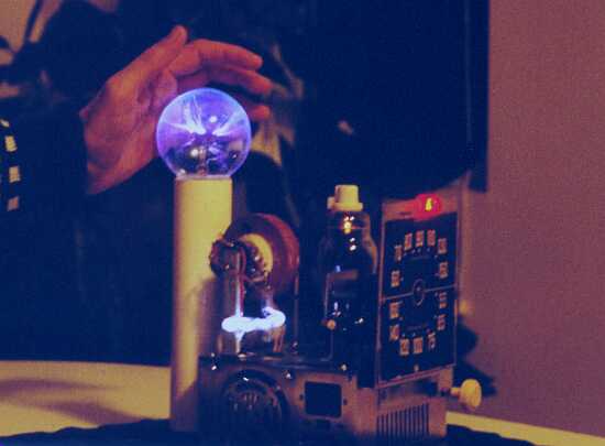
Another view of G'Zot!


