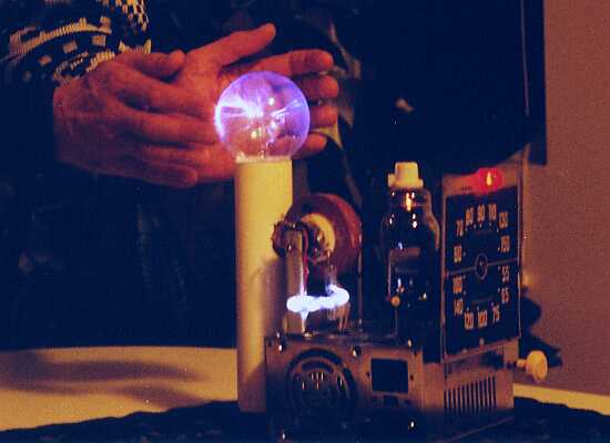
"G'Zot!" Plasma Globe under normal room lighting
2: HOW IT WORKS
A schematic of G'Zot! is shown below. A larger image without anti-aliasing is available by
right-clicking here or on the image, and opening it in a new
window. (Or save link/target to disk and print it out using any suitable image viewer.)
"G'Zot!" schematic
The central component is an old television "flyback transformer". You'll have to find
one that was intended for use with older tube (valve) TV sets; the modern ones might be useable,
but will typically be a lot more difficult to deal with. We don't, however, use it in its usual
role of sweep generator at 15.75 kHz. Instead, we operate it at the self-resonant frequency of
the secondary, (typically 40 - 60 kilohertz) allowing it to give considerably greater output
voltage than usual. My estimate is that output voltage of the prototype is on the order of
30 kilovolts.
The primary of the transformer is driven by the plate circuit of a typical TV sweep tube. I
used an old coke-bottle style 6GB6 (because I happened to have just one, and it looks cool).
A #47 lamp in parallel with a small resistor in the cathode circuit gives a visual indication
of relative cathode current, and functions as a pilot light. This arrangement also gives a
slight amount of cathode biasing. However, if this were the only source of bias, the tube
would self-destruct in very short order.
Most of the grid bias is obtained using "grid-leak bias." The grid is driven from
an external oscillator (using a 6C4 triode) via a coupling capacitor (C12) and grid-leak
resistor (R12) to negative supply. During the first few cycles of operation, the grid of the
final will be driven positive, causing it to draw a considerable amount of current. This
charges C12 until a point is reached where the current draw during positive peaks is just
enough to replenish the charge lost via the grid-leak resistor. As a result, the tube actually
spends most of every cycle at or near cutoff, with brief, fast pulses near the positive peaks.
This is called "Class C2" operation; "C" because the tube conducts for
less than 1/2 of the input waveform, and "2" because the grid draws current during
part of the conduction cycle.
The oscillator is a standard "Hartley" configuration, in which a tuned circuit
(a parallel connection of a coil, or "inductor" and a capacitor) is
connected via the grid and ground, and a tap on the the coil is connected to the cathode.
Cathode current flowing through the tapped portion causes positive feedback, resulting in
continued oscillation at approximately the resonant frequency of the tuned circuit.
Again, grid-leak bias is employed to bias the oscillator tube. This also has a self-levelling
effect with changes in supply, tube type and condition, frequency of oscillation, and other
variables. Let's say that the output of the oscillator decreases for whatever reason; this
will decrease the voltage swing at the grid, causing the average bias level to decrease (i.e.
become less negative). This, in turn, causes an increase in plate current, and therefore
tube gain, partially offsetting the decrease in output level.
The power for the valves' filaments is provided in a somewhat unusual manner. Two 12 microfarad,
200 volt metallized mylar capacitors are connected in parallel, for a total capacitance of
24 microfarads. This is, in turn, connected in series with the tube heaters. The capacitor
essentially forms a current source, since the supply voltage (120 VAC) is so much greater than
the total filament voltage (18 volts). This current can be approximated as Vs*2*Pi*f*C, or about
1.08 amperes (at 120 VAC, 60 Hz). In practice, the current source is not perfect
because of the 18 volt drop across the heater string, so the actual current will be about 0.9
amperes -- exactly what is called for by the 6BG6 tube.
The 8.2 ohm resistor in parallel with the filament of the oscillator tube diverts about 0.6
amperes, resulting in the specified 0.3 amperes through the filament of the 6C4. This use of
a capacitor as a current source is very efficient, since the current through the loop will be
almost 90 degrees out of phase with the applied voltage. There is therefore very little energy
wasted as heat, as would be the case with a current-limiting resistor.
The voltages for the other tube elements are derived from three separate, yet simple, B+ power
supplies. Diodes D1 and D2, together with capacitors C3 and C4, form a voltage doubler circuit
giving about 300 volts DC relative to the "neutral" side of the AC line. This
provides the B+ supply for the oscillator, and also the plate bias for the output tube.
The primary of the flyback transformer provides the plate load.
The second supply is a simple negative supply consisting of D3 and C5, providing about -150
volts DC for the cathode of the 6GB6. Note, therefore, that the effective plate supply for this
tube is therefore about 450 volts. Capacitor C6 gives additional filtration for this B+
voltage.
The third supply is similar to the second, consisting of D4 and C11, and providing about +150
volts for the screen grid of the output tube. Note, as before, that the actual screen-to-cathode
voltage will be on the order of 150 volts higher due to the cathode being biased at -150 volts.
The screen circuitry is completed by resistor R6 and bypass capacitor C13.