
|
|
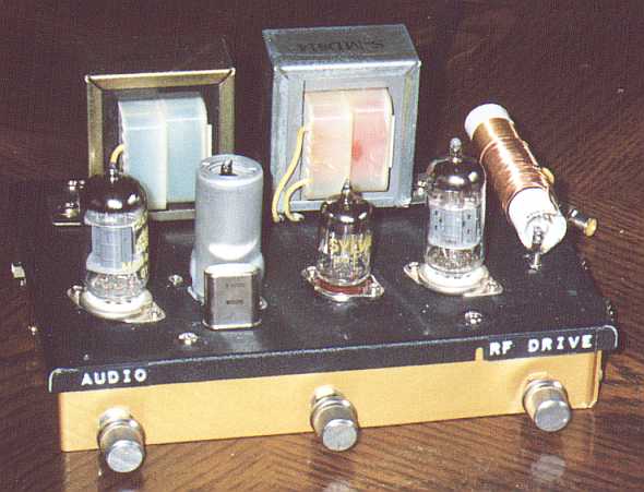
The "Goldberg" (4 tubes) |
|
Here's the ultimate crystal-controlled low-power AM transmitter. It
incorporates a superior audio preamplifier stage, allowing better control of
loop feedback. It also includes an effective RF amplifier stage which boosts the
maximum output by 5 dB, to about 10 milliwatts. This is enough to improve the
range by about 73%, or be enough to drive a linear amplifier such as that
described later in this article series.
|
|
This is the Deluxe Edition of the pentagrid-based home transmitter. It's named in honour of Rube Goldberg, the wonderful cartoonist whose complex contraptions still amuse and delight. Its tongue-in-cheek name aside, this is a great little transmitter that's worth the extra cost and effort to build. It even replaces the detector diodes in the feedback network with a 6AL5 dual vacuum diode. |
| Here is an improvement on the "Bean Counter" design, and is about as far as the pentagrid transmitter can readily be taken. The oscillator (at 1630 kHz in this case) is followed by a mu-follower RF amplifier stage which isolates it from the antenna, gives added harmonic suppression, and provides power gain. The output is, as before, sampled and detected, and fed back to the inverting input of a differential pair input amplifier. Up to about 10 dB of negative feedback can be applied, improving the linearity even further. A trapezoid display on the 'scope (applying modulated RF to vertical and raw audio to horizontal) reveals no visible non-linearity up to 90% modulation. |
|
|
Note that this transmitter uses about twice the B+ voltage of any of the
previous designs. This is to accomodate the higher requirements of the
mu-follower RF amplifier, and to help linearize the performance of the
short-tail-pair differential audio amplifier. However, the supply is set up
as a split (bipolar) supply, which allows us to ground-reference the output
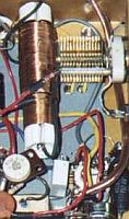
tank coil. Note that the two tanks L1/C5 and L4/C8) should be on opposite
sides of the chassis, and at right angles to each other, to avoid the
"tuned plate - tuned grid oscillator" syndrome that could otherwise
result. By ground-referencing the output tank, we can mount it on the top of
the chassis without worrying about curious fingers (or yours!) getting an
unpleasant shock.
Here's the power supply. It still uses the back-to-back transformer idea, but this time uses a pair of 18V, 1.5A transformers salvaged from 2-way radio chargers, that happened to have split primaries for 120/240v operation. That's also why I used the DC filament rectifier/filter, to boost the voltage from 18VAC to about 24VDC. An off-the-shelf solution would be the Hammond 266J24, you can omit the DC filament supply portion, and run the series heater string directly from the 24 volt AC output. |
|
|
If you're using a short "wet noodle" antenna, use the high-impedance (600 ohm) output. If you're using a long-wire quarterwave or other tuned antenna, use the 50 ohm output. Carrier power is a solid 10 milliwatts (or more, depending on B+. By increasing from 130v to 150v, output power was increased to over 15 mW). Input sensitivity at maximum negative feedback is about 1 volt RMS for full modulation. A couple other minor points that aren't immediately obvious:
Tuning this circuit for best performance is best done using a cathode-ray oscilloscope (CRO), a basic 5 MHz 'scope is just fine. Do your initial setup without an antenna connected, there is enough loading provided by R11 for initial tuning. Connect an adjustable sine generator (1 kHz) to the input of the circuit, and your 'scope lead to the 50 ohm antenna output connector. Also, on most 'scopes you'll also have to run the audio signal to the horizontal sync input, since locking on the audio portion of an amplitude modulated RF signal is difficult at best. Turn the audio gain pot to zero. Set the feedback control to zero. Gradually turn up the RF Drive control until you get a visible carrier on the 'scope. Alternately tune C5 and C8 for maximum output. If maximum output occurs at minimum capacitance, you'll have to pad the tuned circuit(s) with fixed caps. If maximum output occurs at maximum capacitance, you'll have to take a few turns off the appropriate inductor(s) (L1 and L4). Now gradually turn up the audio gain pot. You should see the modulation on the RF signal. Alternately adjust the RF Drive pot and Audio Gain, such that you get a symmetrical AM envelope, with the maximum possible modulation depth without clipping. This is one of those exercises best learned by doing, once you play around with the adjustments you'll start to understand how each control affects the output. Finally, turn up the feedback control. You'll have to compensate for the lower gain by increasing the Audio Gain pot (but don't touch the RF drive pot!). See how much cleaner the signal becomes at high modulation? When you've gotten the hang of it, attach your antenna and repeat the tune-up procedure. You might find that a slight de-tune of C5 and/or C8 will improve the symmetry of the top and bottom half-cycles of the modulated envelope. Another way of using your 'scope to monitor your signal is to use it to make a trapezoid display. Apply your RF signal to the vertical plates as before, but connect your audio input to the horizontal plates. Perfect 100% modulation will show up as a perfect triangle; less than 100% becomes increasingly more trapezoidal in shape. You can judge linearity by the straightness of the top and bottom edges of the trapezoid, and see even brief excursions into overmodulation as flattening or fold-over on the left and right sides. 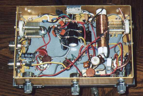
After you've had the transmitter working for awhile, and have convinced yourself that the feedback mechanism works, you will probably be running at the maximum feedback level all the time. So why even have a pot there? Here's a modification you can make that transforms the feedback control into a pre-emphasis control. In the early days of AM radio, there was no pre-emphasis (at least not intentional). FM radio, on the other hand, has almost from the start pre-emphasized the high audio frequencies to improve the noise level. The receiver applies the necessary de-emphasis to compensate, in the process reducing noise (which is mostly high frequencies). In recent times, however, it's become common practise to pre-emphasize AM broadcast signals also, simply to brighten up the sound. To my knowledge, there is no standard for this as there is for FM, and is up to individual stations to apply as they see fit. Modifying the circuit as shown below changes the feedback pot to act more like a pre-emphasis control. Instead of feeding back all frequencies equally, the feedback network now favours the low frequencies, causing a greater gain reduction at lower frequencies, hence pre-emphasizing the higher frequencies. I find that the most pleasing sound is achieved at about 2/3 rotation of the PRE-EMPH pot. |
|
 |
 |
 |
BACK | INDEX | NEXT |