
|
|
"The Muntz" (1 tube) |
|
An AM transmitter using only one tube? Yes, and a very commonly available one
at that. This circuit is a bare-bones transmitter that, with a 10-foot (3 meter)
run of wire as an antenna, will readily transmit an AM signal to nearby radios.
What's more, it doubles as an accurate and convenient 1 MHz marker generator for
aligning shortwave radios!
|
|
The classic 6BE6 tube (and its 12 volt variant the 12BE6) was extremely common throughout the vacuum tube's latter "glory days". It was based on the earlier octal 6SA7/12SA7, which was functionally equivalent. Its purpose in life was to be the local oscillator and mixer in AM radios, and a kazillion of them were made to fill that purpose. But that's not all it can do! With only a few external parts and suitable power supplies, it forms a complete stand-alone AM transmitter! |
|
The first circuit is the
"Muntz" version of
a common one-tube transmitter using a 12BE6 pentagrid converter (a.k.a. heptode).
This marvel of engineering is at the same time an oscillator, mixer,
and amplifier -- all in one valve structure.
Since its intended purpose was as a converter for superheterodyne receivers, its output power capability is quite low; in practise, about 3 milliwatts (into a 50 ohm load). With a short "wet noodle" antenna, the actual radiated power will be a great deal less. It's enough, however, to give good reception within a radius of about 30' (10 meters). This is one case where the practise of "tube rolling" (trying different samples of the same type) really pays off. If you have an oscilloscope, you can monitor the RF output while changing the level of a constant audio signal. There will be significant differences, and a good 12BE6 works amazingly well, achieving up to about 80% modulation. (Keep in mind that the difference between 90% and 100% modulation is less than one dB.) Robert Casey has done excellent work capturing 'scope traces using the 6CS6 pentagrid converter. His conclusion is that these are superior to the ordinary run of 6BE6/12BE6s. However, since I had about a dozen of the 'BE6s, I was able to cull the best of them and achieve similar results. There's a certain nostalgia to these circuits; I used to build them as a teenager, but never with crystal control. They were all along the lines of the "Gypsy" variant, using a variable capacitor and inductor to tune the oscillator. The modified Colpitts scheme shown here worked right away, and is stable and robust. |
|
|
The circuit around the first grid (pin 1) and cathode (pin 2) forms the
basis of a crystal-controlled Colpitts oscillator. Feedback is from the
cathode circuit to the grid circuit via the capacitive divider C2 and C3.
C3 is variable, to allow exact tuning to 1.00 MHz. (Needless to say, you'll
have to change the crystal frequency if you have a station at 1000 kHz in your
area.)
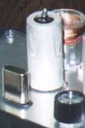
The crystal may be the most challenging item to find. If all else fails, you can get it through any NTE distributor as NTE 650. (Not exactly cheap, though; if you poke around, you can probably find cheaper sources.) Grid 2 acts as a "virtual anode" for the oscillator. Note that it's essentially at RF ground, shielding the remaining grids and the plate circuit from the oscillator portion. Similarly, there's another grid (G4) tied to the same point, isolating G3 from the rest of the tube. G3 is our audio input. The signal applied here mixes with the oscillator current, causing an amplitude-modulated RF signal to appear at the plate. A tuned circuit in the plate is used to peak response, maximizing output and helping to suppress harmonics. However, with only one tuned circuit, there is still plenty of harmonic content. The second and third harmonics are down only about 20 dB, with higher harmonics dropping off. This suggests an excellent alternate usage for this little transmitter: a marker generator for aligning shortwave receivers! Its signal will appear at 1 MHz, 2 MHz, 3 MHz, etc. up to a practical maximum of about 15 MHz. Tuning the circuit is very simple, and can be done by ear if necessary. Connect your antenna and audio input source, and monitor the signal on a nearby AM radio. Tune the one adjustable capacitor for maximum signal, and adjust your audio level for a clear, loud signal without distortion. If you have an RF probe or oscilloscope, you can use them for a more exact tuning adjustment. I don't have an actual photo of the Muntz, since it was later morphed into the Bean Counter variation, covered next. |
 |
 |
INDEX | NEXT |