A HIGH PRECISION TUBE PHONO PREAMPLIFIER
by Fred Nachbaur, Dogstar Music ©1998, 2001
3A-4: PREAMPLIFIER AC FEEDBACK
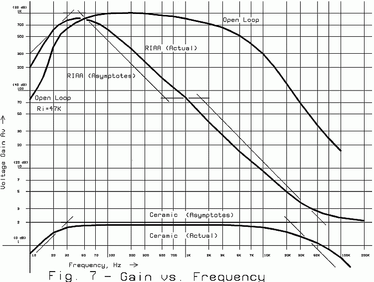
So far we have a pre-amplifier with an open-loop passband gain of about 60 dB, with 3-dB corners
at about 40 Hz and 2 kHz. (See Fig. 7.) While the low-frequency end isn't bad, the high-frequency
end is pretty awful. This is partly because of the compensation intentionally introduced by R115
and C108 and partly because of tube electrode and circuit wiring capacitances. Not to worry, our
bandwidth automatically increases again when we apply negative feedback, just as it does with
solid-state compensated op-amps.

Fig. 7: Preamplifier Open-Loop and Phono Gain Curves
As hinted already, this circuit behaves very much like an operational amplifier (op-amp). But
before we get on with designing feedback networks, we'll point out the ways in which it is not
like an op-amp:
- a) Open loop gain, although quite high, cannot be considered infinite as in many solid state op-
amp devices.
- b) The circuit exhibits a large output-to-input voltage offset (on the order of 290 volts). Any AC
feedback elements between output and input therefore have to include DC blocking capacitors.
The alternative would be level-shifters, which would in my opinion be an additional complication
(and expense) without commensurate rewards in terms of performance.
- c) The DC voltage at the feedback input is non-zero (about 27 volts in practise), so again there is
a need for DC blocking. The point marked "ACG" (AC Ground) is provided for convenience, acting
as a virtual ground for AC, at the same DC voltage as the inverting input.
The not-quite-ideal Tube Opamp
Keeping these restrictions in mind, we can use the formula for the classic non-inverting op-amp
to approximate our gain with feedback. Note that the inverting input (-IN) has a 47K resistor
(R113) to "AC Ground". This is our "default" value for input resistance to the feedback input. Let's
call that resistance Ri, though it can be considerably higher, as needed. The bare-minimum
feedback network would consist of just a single resistance (we'll call it Rf ) in series with a
DC blocking capacitor between output and -IN. The theoretical gain with feedback would then be:
Av = ( Rf / Ri ) + 1
For instance, let's compute our gain if we connect a "bare bones" feedback network consisting of a
430K resistor in series with a DC blocking capacitor between "OUT" and "-IN". That is, Rf / Ri =
9.15, so our gain would be 10.15, or about 20 dB.
The feedback elements do not have to be pure resistances; the above formula could be
generalized to include complex impedances.
Av = ( Zf / Zi ) + 1
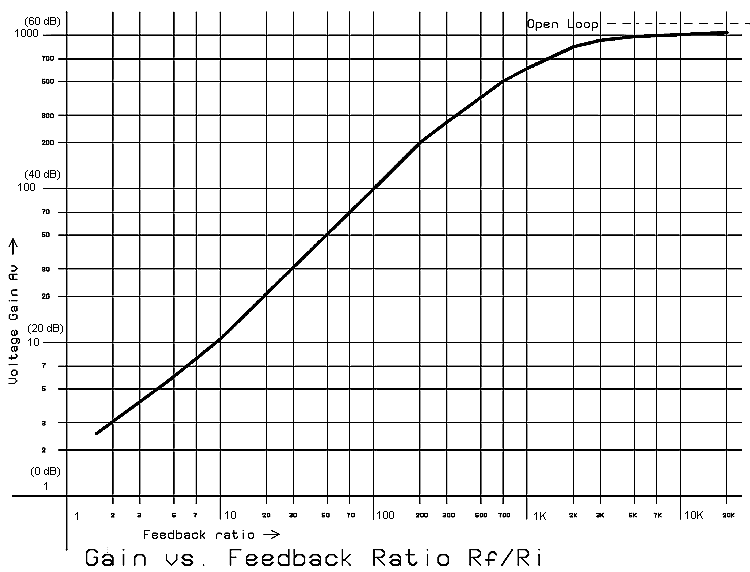
The circuit's actual performance follows this predicted formula very closely, verifying that our
gain-matching shortcut described earlier works just fine. See Figure 6 for an actual plot of the
prototype. The slight curve at the low end is caused by that "+1" factor in the equation; as Rf / Ri
increases, that factor becomes less significant, and the graph approaches a straight-line
relationship. However, at gain settings above about 200 (46 dB), the relationship begins to fall
apart as we approach the amplifier's open-loop gain. Incidentally, this gain setting is also the
practical maximum as regards frequency response; the 3 dB corner at this gain will be on the
order of 16 kHz.

Fig. 6: Preamplifier Gain vs. Feedback Ratio


