A HI-FI VACUUM TUBE AMPLIFIER
by Fred Nachbaur, Dogstar Music ©1998, 2000
3-A) PREAMPLIFIER STAGES: OVERVIEW
Considerable effort was taken to design a preamp that is as clean as possible to satisfy discerning
audiophiles, while maintaining a relatively low parts count to satisfy limited budgets. It should be
noted at this point that, while the discussion is in the context of the full integrated amplifier,
there is no reason why you couldn't build standalone preamps for specific applications using this
design.
The phono/mic preamps and the tone control/line preamps use a universal preamp module with
high gain (about 60 dB), and differential input stages that allow for differential input (as for
balanced mic preamps) as well as either inverting or non-inverting single-ended applications.
Frequency response shaping and gain setting are accomplished using the appropriate feedback
networks.
The schematic diagram of the phono/mic preamp is shown in Figure 2, and the tone/line preamp
section is detailed in Figure 3. Note that these are identical except for the feedback elements. The
phono preamp equalisation is accomplished using a small "daughter" card directly on the main
board; the mic/line equalisation is accomplished using point-to-point wiring to the gain trim
controls; and the tone control equalisation is done on a separate card which include the tone
control pots.
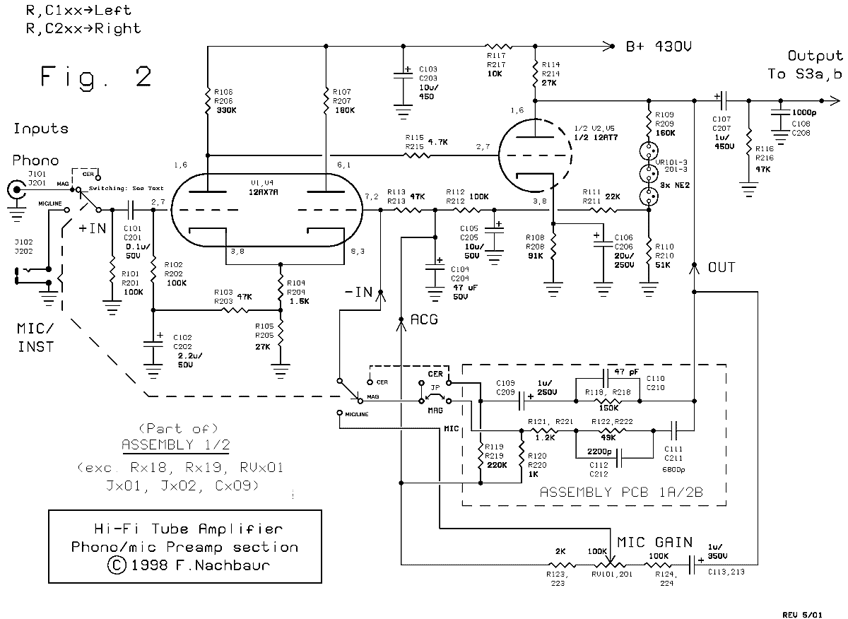
Phono and Mic/Line Preamplifier
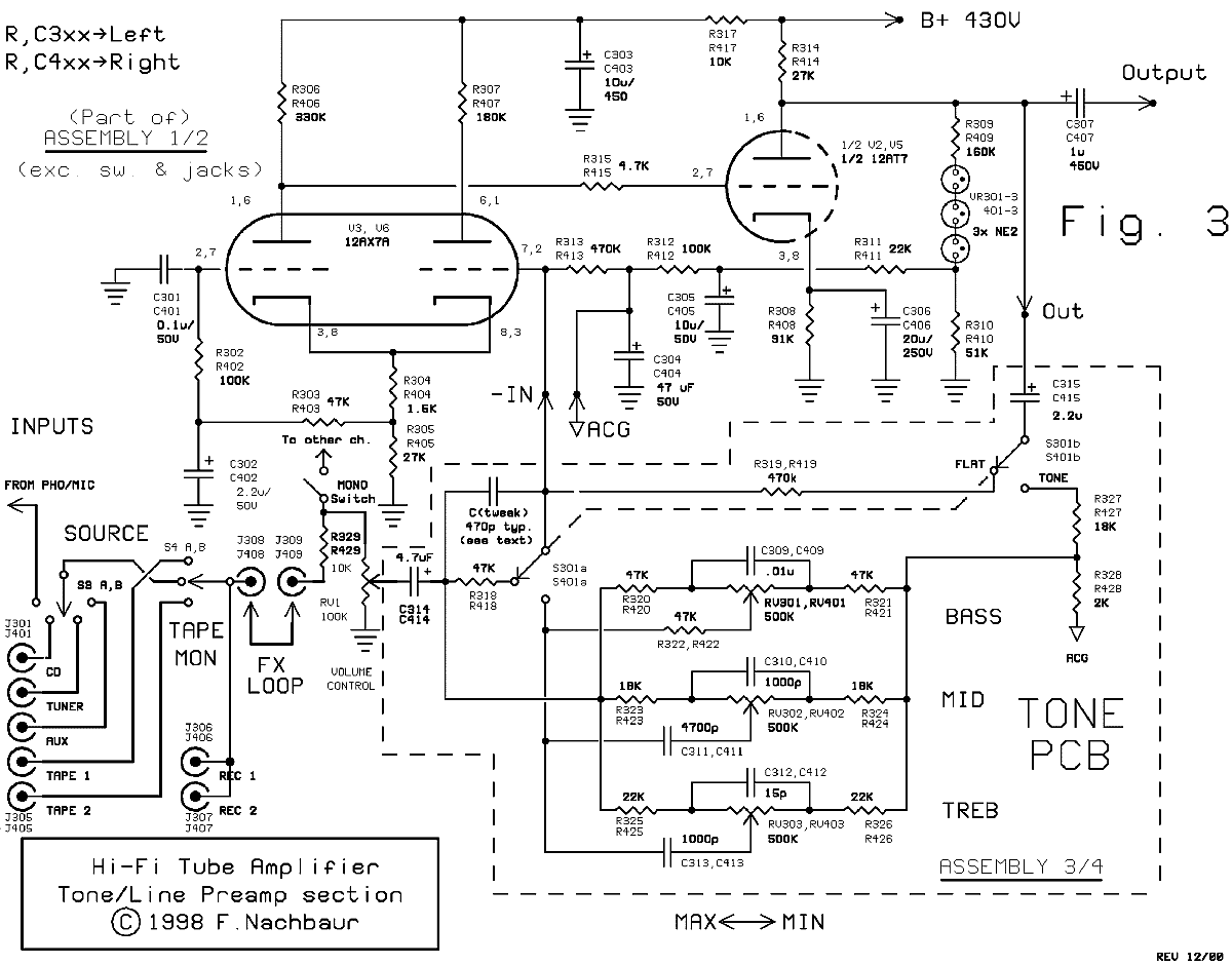
Tone Control Line Amplifier
The main circuit board was designed to be virtually universal in applicability. Small outrigger
"feedback cards" are used to customize the response to almost anything you might need. Figure 6
plots gain vs. feedback ratio for the non-inverting configuration as used in the phono/mic preamp.
There is an obvious linear relationship, except at high gain. (The "porch" at the low end is due to
the "+1" when using the non-inverting mode; see below for further details. In the inverting mode,
as used in the tone preamp section, the relationship remains linear at low gain settings.)
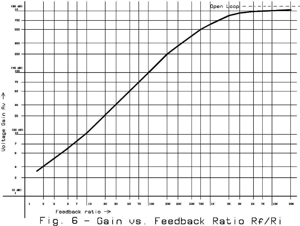
Preamplifier Gain vs. Feedback Ratio
As detailed here, the phono/mic preamp is selectable (using a jumper or switch) between magnetic
phono (RIAA equalization, high gain), ceramic phono (flat response, low gain). An external switch
or switching mic input jack selects between the phono and mic/line (flat response, variable gain)
modes. See Figure 7, which graphs open-loop response and the two closed-loop phono curves.
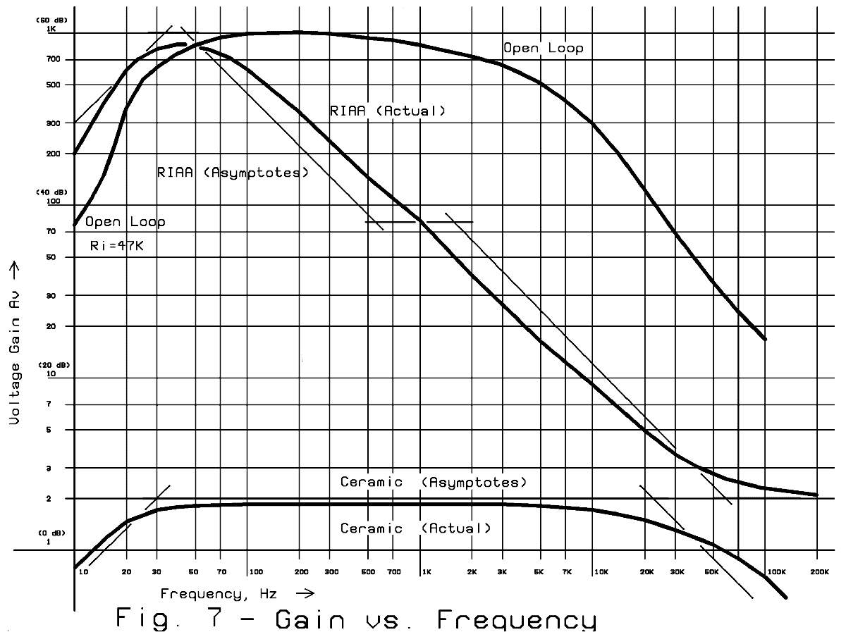
Open-loop, Magnetic Phono and Ceramic Phono Response Curves
There is no reason why you couldn't adapt this universal preamplifier module for any other
gain/equalization combinations, simply by modifying the feedback networks. (Figure 8 gives a few
ideas, covered in more detail in
Other Preamp Applications.)
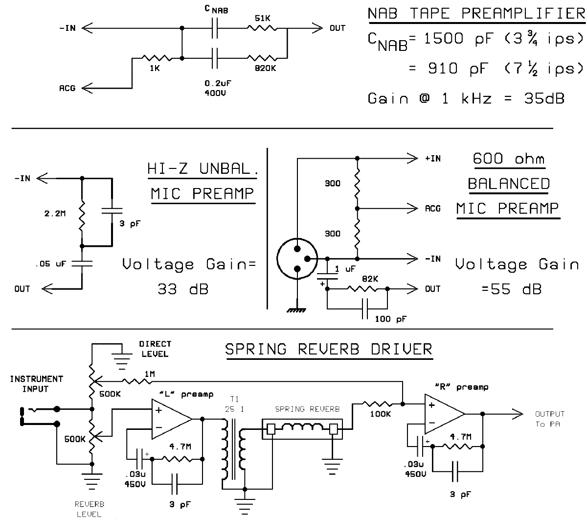
Other Possible Preamplifier Applications
Phono mode
In magnetic phono mode, the RIAA curve is achieved by using negative feedback to decrease the
gain at higher frequencies, according to the RIAA specification. The result is that the amplifier
runs almost open-loop (about 60 dB gain) at 40 Hz, and rolls off smoothly to a gain of less than
20 dB at 20 kHz. This means that the "tube sound" caused by even-order distortion will be most
pronounced in the bass region, giving it that warmth that is so highly prized by vacuum tube
aficionados. At higher frequencies, this distortion is increasingly cancelled out by the negative
feedback that sets the gain, keeping the mids from sounding "brassy," and the highs from
sounding "splashy" (two common complaints about open-loop tube amplifiers).
In the optional ceramic cartridge mode, response is flat within 0.5 dB over the audio range, and
voltage gain is set at 5 (about 14 dB). At this relatively low gain, the circuit is very clean and
distortion-free. However, discerning ears may hear a subtle quality of warmth not present in
solid-state gear.
The tube types and their operating points were carefully chosen to minimize power supply
requirements, and to maximize tube life. Both channels together (four preamps) draw only about
15 mA from a 430 volt supply.
Mic/Line mode
The mic/line mode is similar to the ceramic phono mode, in that it is set for essentially flat
response over the audible frequency spectrum. The exception is that a separate "Gain Trim" pot is
provided for each channel. Minimum gain is approximately 1.5 (about 4 dB), handy for line-level
devices such as some older CD players that may not quite have enough drive for the standard
line-level inputs. Maximum gain is over 200 (46 dB) which is plenty for virtually any microphone
or direct instrument input. It should be noted that you should use only as much gain as is
necessary, since frequency response and distortion figures degrade at the highest gain setting.


