The Real McTube II
by Fred Nachbaur, Dogstar Music ©1998, 2001
4: BUILDING THE REAL McTUBE II
The original "Real McTube" was built into a 4 x 6-1/4 x 2" plastic "minibox"
with an aluminum lid for the controls, because I wanted a unit that was as small and portable
as possible. Admittedly, the layout was a little tight. So for the second incarnation, I used
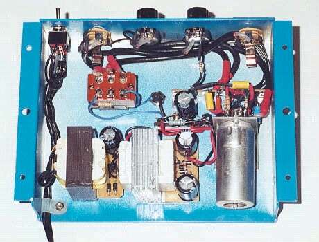
a 6 x 5 x 1.5" aluminum box salvaged from an old telephone relay unit. While the overall
volume is about the same, the geometry made for a less cramped assembly. As in the original,
the tube socket was mounted on an L-shaped metal sub-chassis about 2x2". Biasing and
coupling components were soldered between the socket and conventional phenolic terminal strips.
The terminal strips and tube sockets were secured to the chassis using small bolts and nuts.
Unlike the original version, all components were mounted onto the top case-half, which eliminated
wires between the two halves, making assembly and testing a lot easier. The photo shows the
finished project, and can be used as a guide in your own implementation.
You may prefer to leave yourself a bit more space for experimenting, in which
case I suggest a larger box. With a single 12AX7, heat is not a big consideration
so you don't have to worry about ventilation. Orientation of the tube doesn't
matter either; the 12A?7 family can operate in any orientation (not necessarily a
given for all tubes!)
Be careful about wiring, especially in the comparatively high-voltage plate
circuits. If you're unsure about how the tube connections are numbered, click
here (use your browser's Back button to return to this page
afterwards.) Be sure to use capacitors that will stand the voltage. I suggest staying
away from "carbon composition" type resistors, especially for R4 and R6;
otherwise you can get another classic tube sound - lots of hiss.
Some comments on the power supply: as mentioned earlier, the Real McTube II uses two
inexpensive DC "wall-wart" power supplies, rated at 12 volts DC at 500 milliamperes.
Larger units will work just fine should you happen to have a pair of 800 mA. or 1000 mA. units
in your junkbox, but will require appropriately more real-estate in your project box.
There are two good ways of opening the plastic case in order to retrieve the transformers. The
first method is to carefully cut around the seam using a hacksaw. Be careful you don't cut too
deep, or you might damage the transformer. The other way is to squish the wall-wart in a shop
vise to break the weld along the seam. This appears to work best if you clamp it diagonally,
corner-to-corner; first in one direction, and then in the other. If the ones you happen to have
don't respond well to this approach, use the first method.
You will probably even be able to use the little rectifier/filter PC boards inside the wall-warts.
If yours have four diodes, that's perfect. If they have only two, this means they're using a
centre-tapped power transformer which requires a slightly different circuit approach; see the
alternate power supply schematic if this is the case. Note: both
transformers have to be the same type; i.e. you can't use a two-diode wall-wart and a
four-diode one together.
For the low-voltage rectifier, you can even re-use the diodes that come on the board (D5-D8).
For the high-voltage rectifier bridge, however, you'll have to change the diodes to units with
a higher voltage rating (1N4004 - 1N4007), since the ones in the wall-warts are typically only
low-voltage 1N4001 or 1N4002's. You can also use the existing pads to mount the first filter
capacitor. For the low-voltage supply you could even use the existing capacitor, though I suggest
changing it to a 2200 µF unit (the ones supplied are usually only 1000 µF).
If you're lucky (as was I), you might get boards that already have a place for a second
capacitor, wired in parallel with the first. This can be used to advantage in the high-voltage
supply by installing both 33 µF 160V filter capacitors right on the board, cutting the
trace connecting the positive ends, and bridging the trace with the 2.2k resistor R1. I don't
recommend this for the low- voltage supply, since the considerably larger resistor R2 won't
fit as well.
Note when wiring up the power supply that transformer T2 (the high-voltage step-up transformer)
is wired backwards; what used to be its primary is actually our secondary winding. If you lose
track of which winding is which, look at the size of the wire; the low-voltage side will be
wound with considerably thicker wire. It's these thicker wires that are connected to each other
in this project.
I recommend testing (and debugging, if necessary) the power supply first. At the low-voltage DC
output (no load) you'll typically read about 15-16 volts DC. At the high-voltage output you'll
read about 150 volts under no-load conditions. Be careful about accidental shorts; the
transformers used in these wall-warts won't tolerate much abuse before they burn themselves out.
(If you want to improve your odds, you can put a 1/16 Ampere fuse in series with the AC input.
Since these transformers are designed to self-destruct under fault conditions, the fuse isn't
needed for safety reasons, but might well save you a transformer if you make a wiring error.)
OK so far? Next wire up the filament lines. The output from the low-voltage supply should connect
to pins 4 and 5 (which is which doesn't matter) of the tube socket, with the wires twisted together.
At this point the tube should light up when you energize the power supply. At this point you can also
wire up the LED and its dropping resistor R10. Note that your voltage between pins 4 and 5 will now
be in the range of 12-13 volts, and the high-voltage supply will also be dragged down (generally to
about 145 volts). To avoid an unpleasant surprise as you're working on this or any tube circuit,
discharge the high voltage capacitors after turning off the unit and unplugging it from the
wall socket. The best way to do this is to clip-lead a 10K resistor between the positive and
negative terminals of the power supply, and leave it on for several seconds before proceeding with
your work. (Don't forget to unclip it before applying power again!)
Once the power supply is working, wire up the ground lines. The grounding method is very important
in minimising hum and noise. Tie all grounds to a common point not connected to the chassis.
Connection to the chassis is accomplished at the input and output jacks only. The following
points should each have their own direct wire run to the central grounding point (one of the
ungrounded terminals on your terminal strip): This terminal should be fairly close to the tube
socket, so that the resistors from the tube socket to ground will reach without having excessive
length.
-
V1 (12AX7) tube socket pin 9 (with a wire link to the centre-post if the socket has one).
-
Negative lead (B-) of the high-voltage plate circuit power supply.
-
Ground lead of the input jack J1.
-
Ground lead of the output jack J2.
-
Ground legs of the two volume potentiometers. Looking at the pot from the back, with the three
legs pointing upward, this will be the terminal on the left.
-
Resistor R3. Solder the other end to pin 2 of the tube socket. Looking at the bottom of the socket,
the pins are numbered clockwise from the empty space.
-
Resistor R5. Solder the other end to pin 3 of the tube socket. Also wire capacitor C7 between these
two points, negative end to the ground lug.
-
Resistor R7. Solder the other end to pin 8 of the tube socket. Also wire capacitor C8 between these
two points, negative end to the ground lug.
-
Finally, be sure that there is a good connection to the chassis at the two input/output jacks.
All signal lines, i.e. the lines to the input and output jacks, gain potentiometer RV1, and
to the stomp-switch contacts, should be good-quality shielded cable. (These runs are shown on the
schematic with little ground "rings".) RG174 is a good choice, should it be available to
you. If not, use any decent shielded audio cable. Keep other component leads as short as is
practical, mounting the components as close to their associated tube socket pins as is practical.
The input to the first stage is especially critical; we're dealing with a very high input impedance
and low signal levels, and hum and noise pickup is a real concern.
Finally wire up the rest of the components between the tube socket and the rest of the circuit,
using the terminal strip to provide support for components such as R4 and R6 (connect to the B+
terminal), C5, C6, C8, and R8. R9 gets connected directly across the output level pot RV2.
Again test the power supply before plugging the tube into the socket. At pins 1 and 6
you should read about 145 volts DC relative to ground. Between pins 4 and 5 you should again read
15-16 volts DC. (The reading to ground will be indeterminate with the tube out of socket.)
At all other pins your should read 0 volts relative to ground.
If all is well so far, unplug the unit and plug the tube into its socket. (Careful, the
filter capacitors will carry a residual charge under these conditions. To re-iterate, short them
to ground via a 10K resistor for several seconds any time you work on the unit after having powered
it up.) Monitor the B+ voltage at the positive end of C2 and turn the unit on. You should see the
heaters start to glow. After about 10 seconds the B+ voltage should sag a bit as the triodes start
conducting. The B+ voltage at the positive end of C2 should drop no lower than 135-140 volts DC.
Read the voltages on the pins of the tube again. If you used the component
values suggested, your readings should be in the vicinity of the table below:
| Pin | Description | Voltage |
| 1 | Plate A | +108 VDC |
2 | Grid A | -0.001 VDC |
3 | Cathode A | +1.5 VDC |
4,5 | Filaments | 6.3 VDC |
6 | Plate B | +60 VDC |
7 | Grid B | -0.1 VDC |
8 | Cathode B | +0.7 VDC |
9 | Filament | 0 volts |
If the plate voltages are excessively low, or if either of the grids are positive with
respect to ground, power down right away and find your problem. Same goes if
you see blue flashes in the tube, or smell anything unusual. Be sure that you
used good quality mylar or similar capacitors for C6 and C8, with at least a 150
VDC voltage rating.
Assuming that the voltages check ok, power off again and connect the output of
the pre-amp/ distortion unit to your amplifier, and the input to your instrument.
Turn GAIN and OUTPUT to minimum, and power up. Slowly bring up the controls
until you hear signal. Congratulations! You're on your own from here!
4a: Using the Real McTube II
What sound you get from your guitar or other instrument via The Real McTube
will depend greatly on the settings of the various controls; specifically, the
volume and tone controls on your axe, and the GAIN control. The OUTPUT
control has little or no effect on the sound, and is used primarily to balance the
volume of the sound with or without the effect engaged.
Note that both stages are inverting amplifiers; the overall phase of your signal
will therefore not change. However, how you adjust your controls will determine
what portion of your signal gets clipped. The first stage will tend to clip more on
negative half-cycles as the tube reaches cutoff (remember our discussion earlier
regarding cutoff versus saturation). The second stage, however, will tend to clip
more on positive half-cycles, since it sees an inverted signal at its input. By
carefully balancing your instrument controls and GAIN, virtually any distortion
sound from a mild, "warm fuzzy feeling" sound, to a hard "monster metal shred-
head" sound, rife with odd-harmonic distortion, can be attained.
A compressor before the Real McTube will make it easier to get consistent
sounds, but will also greatly affect the change of sound with varying dynamics. If
you have multiple effects, play around with the various combinations. Where you
place The Real McTube in your chain of effects will have a lot to do with the
sound you end up with.
You might want to reduce the values of coupling capacitors C6 and C8. As you
can verify using an oscilloscope, these will have a considerable effect on the
exact nature of the transients that occur during clipping distortion. Lower values
will give a reedier quality, the higher values as shown in the schematic result in a
fatter sound. The circuit is extremely forgiving; take the opportunity to experience
the fascinating, frustrating, flexible and highly subjective world of the vacuum
tube amplifier.
4b: Alternate Power Supply
If your wall-warts contain two diodes and a centre-tapped transformer instead of four diodes
(no centre-tap), wire the filament portion of the power supply as shown below. (Full size,
printable version of the image is available from the
Resources section.) Note that the centre-tap of the step-up
transformer T2 is left unconnected.