Small Dogzilla Amp Logo
August 20, 2002

Part 1:
Control
Supply
Part 2:
Meter
Circuit
Part 3:
HT
Supply
Part 4:
Power
Amp
Part 5:
PA
Driver
Part 6:
Tone
Preamp
[ Part 7: ]
Effects
Section
Part 8:
Line
Preamp
Part 9:
Input
Stage


Part 7: Small-Amp Emulator and Compressor Amp

One of Dogzilla's unique features is the inclusion of a separate small guitar amplifier output stage, consisting of a single-ended 6K6 driving a small, inexpensive output transformer. This is for those times when you might want that characteristic "Fender Champ mic'ed into a big amp" sound.

Another "must-have" feature is a compressor, for those screaming-long sustains, and to equalize output volume at various playing velocities.

Small Amp Emulator:
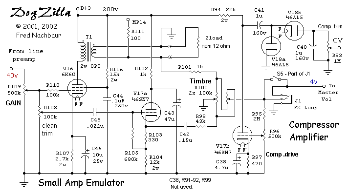
The signal from the main GAIN control is applied to the grid of the 6K6 "Small Amp Emulator." R110 is included in series with the grid to prevent grid overdrive from dragging down the "clean" signal. R107 and C45 provide cathode bias and bypass, respectively. The cheesy minimalist screen supply typical of vintage small guitar amps is provided by R106, with screen bypass provided by C44. A small output transformer scrounged from a table radio couples the plate circuit to the dummy load Zload.

Zload is nominally a 4-ohm, 5 watt resistor. However, other L-R or even L-R-C networks could be attached here to simulate speakers. A real speaker could even be used, perhaps in a "dead box" to reduce its acoustic effect while retaining its sound in the main power amp. What a concept! ;-)

Small-Amp Emulator and Compressor Amp

Schematic, Small-Amp Emulator and Compressor Amp


A sample of the input is also applied to voltage-follower V17a to provide a separate low-impedance source for the "clean" signal component. Isolating the signals in this way reduces potential headaches caused by positive feedback through the mixer (Timbre fader) network. Note that the small-amp emulator (SAE) stage actually has a significant insertion loss; this is because, even though it has significant power gain, the actual output voltage is only about 4 volts peak, with a 18 volt peak input to the 6K6 grid. The "Clean trim" pot R108 is set such that the clean output is approximately of the same amplitude as the "dirty" signal from the SAE.

"Timbre" pot R100 is used to fade continuously from the raw (Clean) signal and the output of the SAE, giving a fascinating range of distortion control. The output of the fader circuit passes through the switched "Effects" jack, to the following stage (active tone control amplifier).

Note that the phasing of the SAE output transformer is such that its output is in phase with the input signal. Similarly, the output of the "clean" CF is obviously in phase. This assures that there is no phase cancellation as the Timbre pot is rotated from one extreme to the other. An interesting variant would be to add a DPDT phasing switch to the SAE output transformer, such that with the pot near the center position, only the error signal would be amplified. (Such an option is a little too rangy for my tastes, though!)

Compressor Amplifier:
The second section of the 6SN7 dual triode V17b is an ordinary common-cathode stage, used to provide the source for the limiter rectifier. Using a dedicated stage isolates the non-linear behavior from the signal path, while making it possible to create a rapidly rising compressor control voltage on sudden increases in signal level. The voltage divider consisting of R96 and trim rheostat R95 sets the level to the compressor amp, and allows for a pre-level adjustment.

The little 6AL5 dual-diode V18 is configured as a voltage doubler at the output of the compressor amp. This approach insures that both positive and negative peaks are taken into account in what is essentially a peak sample-and-hold circuit. The charging time constant is quite fast, on the order of 20 mS; however, the discharge time constant is much slower, on the order of several seconds, giving a gradual recovery from compression. If desired, this recovery time constant can be speeded up by parallelling a fixed resistor or rheostat across the DC control voltage adjustment pot R93.

The control voltage produced by the compressor amp and rectifier are applied to the control grid of the first preamp stage, a 6K7 remote-cutoff pentode (covered in section 9).


Back Home Next
BACK INDEX NEXT