A HI-FI VACUUM TUBE AMPLIFIER
by Fred Nachbaur, Dogstar Music ©1998, 2000
Note: See also
LTP/CCS Driver Improvements (Sept. 2002)
(Use your
browser's "Back" button to return here)
3C: DRIVERS AND POWER AMPLIFIERS
The driver/PA section is shown in Figure 4. Starting from the output side of the circuit, there is a
more-or-less conventional push-pull pair of 6L6GC's feeding a high-quality output transformer,
which couples the amplifier's output signal to the speaker load. Small value cathode resistors give
a very slight amount of local feedback and help to reduce cross-over distortion. Mainly, however,
these give a convenient test-point for measuring quiescent plate current of each tube. Divide the
voltage across the resistor (in millivolts) by ten to obtain quiescent current in milliamps (this will
typically be 40-50 mA, corresponding to a grid voltage of -72 volts with most tubes).
Fig. 4: Driver and Power Amplifier
At the grids are silicon diode pairs which absorb most of the grid current, should grid voltage
exceed about +1.2 volts. These are for protection during power-up, should the user forget to turn
off the "standby" switch before enabling the main power switch. (Note: there is a "hack" available
in the "Tweaks and Hacks" section that eliminates this problem.) These diodes also effectively
prevent unwanted class AB2 operation which could easily damage your tubes at high signal levels
with low grid bias.
The screen grids are tied to taps on the output transformer, supplied specifically for this purpose.
Such transformers are sold as "ultra-linear" transformers, but it should be pointed out that it's not
the transformer that is particularly linearized by this process, rather it's the local negative
feedback to the screen grids that causes the substantial improvement in linearity (and thereby
reduction of THD). This design also allows us to use substantially higher plate voltages without
damage, permitting higher output power and better overall linearity.
The control grids are direct-coupled to the plates of a differential input pair, using a 12AT7A this
time because of its higher drive capability. Unlike the comparable circuit in the preamp stages,
however, this circuit is exactly balanced by using identical operating points in the two triode
sections of the tube. Also unlike the preamp, it is fairly important that the two sections of the
dual triode be reasonably well-matched. If you find that you have to turn the "balance" control
(discussed later) too far from centre to get equal grid voltages on the two output tubes, try a
different 12AT7A.
Also unlike the preamp circuit, the common cathodes are not current-driven via a large resistor.
Instead, a small pentode is used as a current source.
This pentode, a type 6CB6A, was chosen strictly for its DC characteristics. Any other sharp-cutoff
pentode with similar characteristics will work, with suitable modification to the cathode resistor
values. Its only function is to provide a reasonably constant current to the two differential
amplifier tubes, thus assuring a high common-mode rejection ratio. This also increases immunity
to fluctuations in the negative supply voltage, which is why we can get away with a simple zener
diode reference voltage (though see the "Tweaks and Hacks" section for more about this).
Note that the cathode of V8 is sitting almost at -590 volts, and the cathodes of V7 will typically
ride at about -300 volts. This would present an unacceptable heater-to-cathode voltage on both
tubes, if the same (ground referenced) heater supply were used as supplies the rest of the circuit.
This is the reason for using a separate heater supply. The 5V winding on the power transformer
was nominally intended for the heater of the 5U4 (or similar) rectifier tube, and is therefore well-
isolated from ground. A resistive voltage divider in the power supply biases this heater voltage at
approximately the midpoint between the cathode voltages of V7 and V8. Even at that, we're
pushing the limits of the recommended heater-to-cathode voltage; however, I have not observed
any ill effects because of this, using tubes of varying manufacturer and condition.
The screen of V6 is set at +120 volts (relative to cathode) with a zener-diode regulator, to help
insure the tube's constant-current characteristic. The control grid is set at a variable slight
negative voltage relative to cathode, which gives control over its current output, thereby shifting
the operating point of the differential pair and providing our PA bias adjustment. (Looks like the
long way around to set grid bias, but it's actually very simple, reliable, and in a funny way,
elegant.)
Offset between the differential stages is set with a trimpot in the cathode of the non-inverting half
of the differential pair. This allows us to trim out differences in tubes, and assure exactly the
same quiescent current flows in the plate circuit of both output tubes. Again, if you have to turn
this balance pot too far off centre, use a 12AT7A with better matching between sections.
Note that PA tubes' bias can either be set to a given voltage at the grid of each output tube
(typically -72 volts), or it can be set by adjusting for equal voltage on the cathodes (representing
equal current draw in each section) - typically 40-50 mA. The latter method is probably the
better, unless the tubes are reasonably well-matched. Incidentally, this provides an easy way to
check the match between two tubes, at least as far as emission (and to a lesser degree,
transconductance) are concerned. Set the grids to be equal, and the cathode voltages should be
equal also (within reasonable limits).
A "PA mode" switch allows us to switch in or out a negative feedback network around the whole
circuit. Since the circuit includes the driver tubes, PA tubes, and output transformer, any non-
linearity in any of these components is greatly reduced. The main advantage, however, it
reduction in equivalent output resistance, which reduces the depression in midrange response on
most dynamic speaker systems. Effective series resistance (open-circuit voltage divided by short-
circuit current) of the prototype was reduced from about 18 ohm to approx. 8 ohms -- ideal for 8-
ohm speaker systems. (It should be noted that this does not affect the "impedance match" as
applied to maximum output power capability.)
This feedback network can be bypassed for that "classic" tube sound, should you desire to do A-B
comparisons. You might actually prefer the "classic" sound, especially on older rock `n' roll
material. To allow us to set the same gain in "classic" mode as in "clean" (feedback) mode, a gain
trim control is provided for the "classic" mode.
The open-loop voltage gain of the driver/PA circuit is approximately 25 (at the 8 ohm output
tap). We use feedback to reduce this to a gain of about 4, so it is reasonable to expect about
a 5:1 improvement in noise and distortion specs. Given that the open-loop distortion of a pair
of 6L6GC's in AB1 mode is rarely better than 1%, we can reasonably expect to lower this to
about 0.2% by using this "dynamic compensation" system. Another way of stating this
is that the total level of distortion will be reduced by well over 10 dB... nothing to sneeze
at!
100 ohm Resistor R515 (615) is shown at the output of the PA; its sole function is to improve
your odds of not blowing the finals and/or arcing the output transformers should you open-circuit
the speaker terminals when operating at high volume. If you're careful about this, you may omit
this resistor, since it does rob some output power and can get quite warm during high-power
operation. In general, never never open-circuit the outputs of any tube amplifier. Always use a
dummy load (i.e. 8 ohm, 50 watt resistor) during testing.
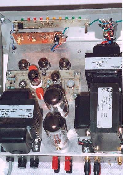
The Power Amplifier circuit, showing the Driver card assembly.


