"Li'l 4x4"
by Fred Nachbaur, Dogstar Music ©2001
2: HOW IT WORKS
THE CLASSIC MINIMALIST AMPLIFIER
We'll start our discussion on the "Li'l 4x4" by first having a look at the classic
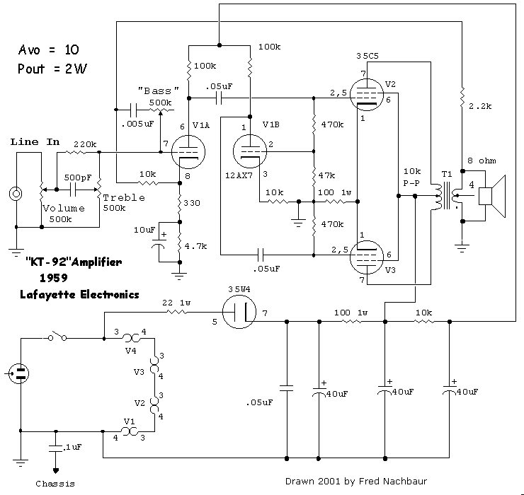
push-pull 35C5 design used in the Lafayette KT-92 amplifier. The schematic is repeated below
for easy reference. If you wish, you can right-click on the image then select "open link
in new window" if you wish to have it available as you read through the text portion of the
article.

Schematic, classic Lafayette KT-92 design
The unit is powered directly from the 120 volt AC line, with no power transformers. Filaments are
wired in series, with the total adding up to 117 volts (35 + 35 + 35 + 12). The 35W4 forms a
half-wave rectifier, which is filtered by a three-stage RC network. The B+ for the output stage
plates and screens are taken from the second capacitor, and the B+ for the preamp and phase
inverter from the third capacitor in the filter.
The input signal to the amplifier is applied directly to the volume control pot, from whence it
passes through a variable high-pass filter (the "Treble" control). When the wiper is
set to minimum, response is approximately flat (though actual frequency response will depend
somewhat on volume control setting). When it's turned to maximum, higher frequencies are favored,
with the lower 3 dB corner at around 1500 Hz. and the higher pole (plateau) around 4000 Hz. For
testing purposes, the volume control was set to maximum and the treble control to minimum, to
minimise the effect of this control.
The output of the volume/treble control circuit is applied directly to the grid of the first
section of a 12AX7 twin triode. A partially bypassed cathode resistor supplies grid bias, while
providing a modest amount of local negative feedback to help linearise the stage's response. A
100k resistor provides the plate load for the preamp stage. The cathode also has a 10k resistor
to the "Bass" control connected to it; we'll discuss the function of these components a
little later, as they are part of the global feedback network.
The output of the first stage is coupled, via a .05 µF capacitor to the grid of one of the
output tubes, connected as a push-pull pair. A portion (about 1/11) of this signal is picked off
using a voltage divider, and is fed to the grid of the other half of the 12AX7 twin triode, which
forms the phase inverter.
The voltage gain of the phase inverter is set to just under 10 by the ratio of plate resistor to
(unbypassed) cathode resistor. Note that the plate of this triode provides an output signal of
comparable magnitude, but opposite phase to the signal on the plate of the preamplifier stage. This
"equal but opposite" signal is coupled, again via a .05µF capacitor, to the grid
of the "pull" half of the push-pull output stage.
It should be noted at this point that this is not the greatest phase inverter circuit ever
invented. Performance can be improved considerably by making the cathode resistor of the phase
inverter adjustable, such that gain can be trimmed to feed exactly the same amplitude of signal
to both halves of the push-pull output pair. This is, in fact, the only modification (other than
the power switch error mentioned earlier) made to this unit for the purpose of comparison testing.
The plates of the 35C5 output tubes connect to opposite ends of a center-tapped output transformer.
The secondary winding feeds the 8-ohm speaker. A tap is also provided for a 4-ohm speaker, but all
testing (and this ensuing discussion) was made using the 8-ohm output tap.
The ungrounded (hot) side of the speaker output is also used as the pick-off point for a simple
but interesting global feedback network. Note that the phase of the signal at the speaker is
inverted from that of the source signal at the grid of the preamplifier stage, and also of the
signal on the cathode. The circuit is interesting in that both the grid and the cathode of the
preamp are used as injection points for the negative feedback signal.
Full-range feedback is applied directly to the cathode by the sum of the 2.2k and 12k resistors. A
portion of the signal is also applied to the grid, via the "bass" control circuit. With
the bass control at minimum (maximum resistance), the circuit essentially does nothing. However,
as the resistance is decreased, more and more of the high-frequency component is fed back to the
grid, causing a decrease of system gain at higher frequencies, and by extension favouring the
lower frequencies. Because of the extreme simplicity of this circuit, there is a considerable
effect on overall gain. As in the case of the "treble" control, all tests and
measurements were made with this control set at minimum (effectively out of circuit).
HOW CAN WE DO BETTER?
Perhaps not surprisingly, classic circuits such as that used in the Lafayette KT-92 fall short of
qualifying for a "hi-fi" designation by just about anyone's standards. Following is a
list of some shortcomings (ignoring the tone controls):
- Unsymmetrical phase inverter un-necessarily degrades even-harmonic distortion figures.
- Relatively low system gain allows only slight negative feedback, and consequent THD reduction.
- Class A operation at low plate voltage allows output power of only two watts maximum.
- Comparatively large noise signal, mostly from 60 Hz power supply hum (and its harmonics).
- Unisolated supply makes the unit unsafe or even unusable in most applications.
All of these issues are addressed in the "Li'l 4x4" design. Starting with the last point
first, we need a transformer-isolated power supply, at least for the B+ circuitry. However, we can
retain one aspect of the line-operated power supply: the direct filament (heater) power for the
output tubes. Since the unit's chassis (and therefore input and output jacks) will be connected to
earth ground, this is safe even in the event of an internal short in the output tubes.
For the preamplifier tubes, however, we use transformed power to help in reducing hum and noise. For
the high-gain pentode input stage, we'll go one step further and rectify/filter the filament
supply.
THE 4x4's POWER SUPPLY
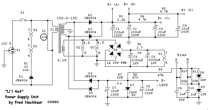
Here is a schematic of the resulting power supply portion of our circuit:

A few points are in order:
- The positive supply is full-wave rectified using solid-state diodes, for better voltage
regulation and lower noise.
- The positive supply is of significantly higher voltage than the line-derived voltage of
classic designs, allowing us to squeeze over twice as much power from the same tubes by employing
class AB1 mode of operation.
- We also have a regulated negative supply of -140 volts, which provides the source for
separately adjustable output tube grid bias. This eliminates the need for a cathode resistor,
and its attendant effective supply drop.
- The negative supply also allows us to improve linearity of the "long-tail-pair"
differential input and driver stages by providing a higher total supply voltage
(about 340 volts).
- Solid-state diodes are used throughout for efficiency and improved voltage
regulation.
- The output tube filament supply is dropped from 120VAC to the required voltage using a
combination of a half-wave diode and a resistor. This results in significantly less excess heat
than using a resistor only.
- The line preamp (V2 = 12AX7) and driver (V3 = 12AU7) filaments are AC powered from a filament
winding on the power transformer, rather than risk introducing hum and noise by placing them in
series with the output tube filaments. The instrument preamp stage (V1 = 4AU6) is taken one step
further by providing a filtered DC filament supply.
- I used a 4AU6 for the instrument preamp stage. Its 4-volt filament allow us to use a two-pole
filter in the DC filament supply, for even greater hum reduction. (The more common 6AU6 could be
used by removing R6 and C6, and increasing C5 to 4700 µF.)
- By suitably changing the power transformer, the circuit can be used with 240 VAC mains. However,
arrangements would need to be made for the output tube filament supply, as direct-line operation
would considerably exceed the maximum heater-to-cathode voltage, and is therefore not recommended.
THE MAIN AMPLIFIER
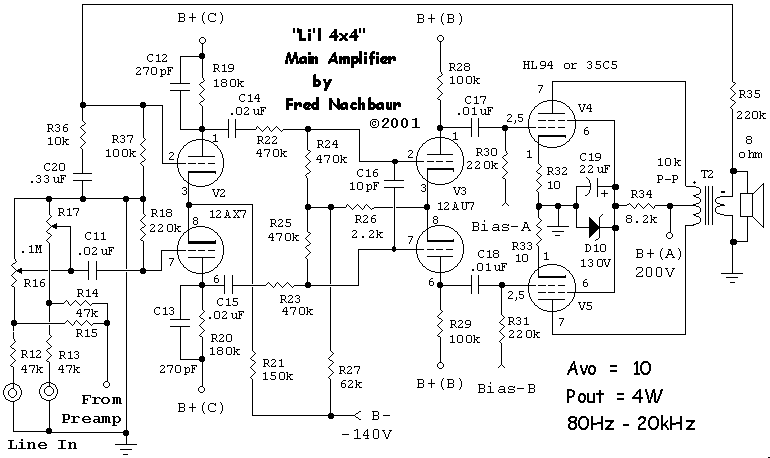
This is the schematic diagram of the "Li'l 4x4's" main amplifier circuitry. This completes
the circuit if you're only interested in line-level input sensitivity.

The first big difference in this design is that the output stage is fixed-biased rather than
cathode-biased. This gives excellent control over the bias point, and also does not "rob"
any range from the tubes' allowable voltage swing. It also allows us to operate the tubes in Class AB1
mode without any bias shifts as either tube is driven close to cut-off.
The use of Class AB1 mode essentially doubles our output power, compared to the KT-92 design; where
the KT-92 barely achieves 2 watts before exhibiting noticeable flattening of the input waveform, the
"Li'l 4x4" puts out a solid four watts before clipping (using 30A5/HL94's). What's more,
the total power dissipation of the tubes is actually reduced! The KT-92 runs at about 65
milliamperes, with a plate-to-cathode voltage of about 87 volts, for a dissipation of 5.7 watts.
The Li'l 4x4 runs a plate-to-cathode voltage of around 180 volts, at 20 milliamperes quiescent,
for a dissipation of 3.6 watts. At full output power plate dissipation increases to about 5.4 watts.
The screen supply has also been considerably improved, using a 130 volt zener diode (or string adding
up to 130 volts). This maintains a constant voltage until total average screen current exceeds about
6 milliamps, at which point the voltage begins to sag in order to protect the tubes from excessive
screen dissipation. Capacitor C19 essentially only becomes significant under this reduced-voltage
condition, preventing screen voltage from varying with applied signal and keeping the circuit in
true pentode operating mode.
Note that the amplifier uses push-pull (balanced) geometry throughout. This greatly reduces
even-harmonic distortion by making the amplifier's response as symmetrical as possible around the
x (time) axis. There is no phase-inverter stage, per se; the two required phases are already present
at the plates of the driver stage (V3 = 12AU7), which is a "long-tail pair" differential
amplifier. The grids are cathode biased by means of a tap on the cathode resistor string. The driver
is in turn fed by a similar long-tail pair differential preamplifier (V2 = 12AX7) with ground-
referenced grids (made possible by our -140V negative B supply). The use of an additional stage
affords a much higher system gain than traditional designs, permitting a much greater amount of
feedback to be applied in order to linearise response.
Furthermore, this circuit employs a feedback topology very much like that used for operational
amplifier designs. The non-inverting input (grid) of the differential input amplifier is used
strictly for signal input. The inverting input is used strictly as a feedback node. The feedback
signal is therefore independent of the input signal, and ensures a constant, near-resistive input
impedance. The feedback input essentially ties to a simple voltage divider from the speaker output,
making feedback calculations relatively straightforward.
Since this was intended as an amplifier for guitar, and since the speaker and output transformer
combination used for this application has a practical low-frequency limit of around 80 Hz, a
low-frequency rolloff of about 50 Hz. was included in the feedback network. Well above this
frequency, the voltage divider consists essentially of R35 and R36. However, at lower frequencies
R36 essentially drops out of the picture, leaving only the much higher R37 as the lower divider
element, increasing the resulting voltage feedback and decreasing gain correspondingly.
The final aspect that we need to address are the low-pass filters formed by C12/R19 and C13/R20.
This is necessary to limit the high-frequency response of the amplifier to prevent oscillation due
to negative feedback. Another such low-pass filter is provided by the dividers R22/R24 and R23/R25,
in conjunction with the input capacitance of the driver stage plus C16. Without such high-frequency
roll-off, the circuit becomes a dandy ultrasonic power oscillator, even at comparatively low levels
of negative feedback. Similarly, the coupling capacitors C17/C18 into the driver stage were chosen to limit low-frequency
response (3 dB rolloff frequency at about 70 Hz) in order to prevent low-frequency oscillation
(motor-boating). Note that both the high- and low-frequency roll-off corners may need to be tweaked
in your particular application, depending largely on your output transformer. With a good transformer
such as the Hammond unit recommended in the parts list, you will very likely get away with less
severe filtration.
TO FEEDBACK OR NOT TO FEEDBACK
I have no intention here of stirring the pot in which cooks the Great Feedback Debate. For those who
prefer designs that are intrinsically highly linear (therefore requiring no feedback) and can afford
this often very pricey hobby, more power to them. However, since this the intent of this design was
to create a high-fidelity circuit using inexpensive low-fi parts, the use of feedback is an
absolute necessity.
I'll be the first to admit that NFB (negative feedback) is a double-edged sword in vacuum tube
applications. On the surface it would appear that the same principles that are routinely used to
make fast solid-state circuits super-linear, could also be applied to vacuum tubes. However, with
tubes such approaches only work under appropriate conditions. For example, the
"Universal Preamp" circuit I developed for high-fidelity
reproduction applications gets away with it mainly because of direct-coupled stages, which reduce the
number of reactive elements that make application of large amounts of NFB challenging, if not
impossible.
The biggest fly in the ointment is the output transformer, required in most efficient tube power
amplifier systems. It is, in my experience, the single largest source of frequency distortion in tube
power amps. What's worse, it can be very difficult to effectively include in global feedback
networks. Both problems can be minimised by using high-quality transformers, such as in the
RA-100 Reference Amplifier project; since the transformer is already of
high quality, not much feedback is required to reduce any remaining non-linearities to tolerable
levels.
However, when using inexpensive output transformers, more feedback is needed to straighten out the
response of circuits using them. The problem is compounded by the fact that such transformers tend
to have high values of "leakage inductance" which introduce a significant positive
reactance even when properly terminated with a load. This combines with distributed capacitance
(negative reactance) to form a self-resonant circuit, with resulting poles that can make the use of
large amounts of feedback virtually impossible.
Another potential difficulty with NFB is that all can be well within the linear region. However, when
the amplifier does reach clipping, the NFB falls to pieces and the resulting distorion is far more
extreme than it would be without NFB.
Finally, because of the multiplicity of poles in most tube circuits, introduction of large amounts of
feedback can in fact increase the distortion on some harmonics (especially higher ones) even
while it reduces the level of others. The end effect is that the sound with large amounts of NFB is
not necessarily better than the sound without it; it's merely different. The situation is reminiscent
of the use of noise reduction on phonograph records, etc. If the noise reduction level is set too
high, the new artifacts that are introduced can be more noticable and annoying than the original
hiss and clicks!
So, in the design outlined here, I did a lot of experimentation to find a viable compromise to suit
my requirements and preferences. The result was a circuit using a great deal more NFB than is
usually applied to such circuits (for example, the KT-92 design), producing an amplifier that
sounds much better than one would guess by looking at its parts list; however, the "price"
is severe instability under no-load conditions (not recommended for tube circuits anyway!) and some
truly astounding artifacts under overdrive conditions (see the next section for the details).
INSTRUMENT INPUT STAGE
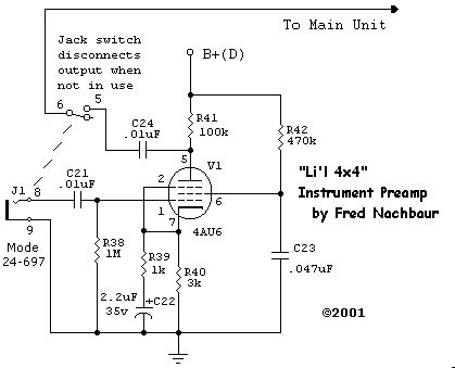
The instrument preamplifier is a completely "stock" pentode preamp design. No surprises
here. The cathode is partially bypassed to give a moderate amount of local feedback to reduce noise
and distortion at the expense of gain. Since the pentode circuit by its nature has a comparatively
high gain to start with, it's in my opinion a worthwhile trade. Gain is further rolled off in the
bass region, with the 3 dB knee at about 70 Hz.
I used a 1/4" input jack with an isolated switch, which disconnects the output of the preamp
stage from the line amplifier when no instrument is plugged in. This eliminates any possibility of
hum from the preamp being fed through to the rest of the amplifier, when not actually being used.


