PAiA "Theremax" Modifications
Part 1: ©1998 by Fred Nachbaur.
"Theremax" is a Trademark of
PAiA Electronics for their
Theremin and Gestural Controller kit. Click on the link for
further information. The modifications documented here have not
been explicitly or implicitly sanctioned by PAiA Electronics.
The purpose of this page is neither to give a comprehensive review of this popular
theremin design, nor to be an introduction to the fascinating and quirky world of
theremins in general. If you're wondering "What the heck is a theremin?",
check out the links on the index page.
That being said, there are a few comments that bear making before we get on with
improving an already excellent design. The "Theremax" is a nice
implementation of the classic Theremin idea.
It does everything that the more traditional designs do, plus it contains added
circuitry (i.e. "frequency- to- voltage converters," or more simply F-V's)
to convert the pitch and volume signals into "CV" (constant
voltage) signals that can be used to control external devices. For this reason
its designer has opted to call it a "Gestural Controller."
The three things that impressed me most about Theremax are:
-
Theremax handles volume unlike any other design I've seen. Rather than using a simple
LC circuit that is detuned by hand proximity, it employs a separate oscillator pair
with its own frequency-to-voltage converter to effect the volume change. The result
is a dynamic range vastly greater than that afforded by previous designs such as the
SWTP design informally adopted by TECI (Theremin Enthusiasts Club International).
-
Theremax uses velocity (derivative of volume) to modify the sound by
introducing asymmetry (and therefore even-order harmonic distortion)
into the VCA. The idea here is to give a feeling of articulation on notes that are
played with high velocity, much as a piano sounds different when struck hard than when
played softly.
-
The "Timbre fader" was another feature that convinced me
to buy, work with, and help promote this fascinating device. This allows a transition
between the classic sine-wave sound, and a harder, more penetrating square-wave sound.
In practise, however, I found the last two features slightly lacking. However, after
implementing the modifications detailed below, (and adding my "DIS*PLAYER"
circuit), I was completely content with the instrument's performance.
Timbre Control Modification
As supplied, there is a noticable drop in volume when fading all the way to the
right of the Timbre pot (square-wave sound). Since this is easy to fix, I'm
mentioning this one first.
Simply replace R40 with a lower value (I used 150K). This gives a smoother, more
even transition between sine and square wave sounds. As often happens in the wonderful
world of mods, the left end of the pot now gets a little touchy, with the square-wave
sound coming up quite rapidly. Replacing R81 (the 100K Timbre pot) with a log-taper
(audio taper or "A" type) pot of the same value as the original solves that little
inconvenience quite nicely.
Velocity Articulation Improvement
The other shortcoming was that, to my ear at least, the timbral change
on rapid attack was hardly noticeable. I verified that the circuitry was
working by using my scope to check that, indeed, the operating point of
Q11 was being shifted by the increase of velocity voltage on the wiper
of the velocity pot. Another problem was that the velocity voltage took
a long time to decay after an attack. Investigation showed that part of
the reason was leakage current through the 10 µF electrolytic C25 (quite
a large value), and part of it was just the high impedance in the
circuit.
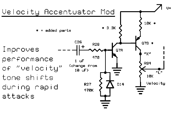
Both problems are solved by the following modification. Refer to the
diagram
shown, while following the step-by-step instructions that follow.
IMPORTANT NOTE:
While
the modification is perfectly safe for your instrument if followed verbatim, you should
not attempt this if you're uncomfortable with cutting circuit traces or soldering parts
"dead-bug"-style on your instrument's circuit board. Also, this modification
should only be undertaken once you're certain that your instrument is functioning
correctly as per the manufacturer's instructions.
- Cut the trace running between the collector of Q7 and the collector
of Q6.
- Cut the trace running between the base of Q7 and the junction of R27,
R28, and D14.
(These are the only two trace cuts that will be required.)
- Resistor R27 is technically no longer needed, but it does no harm to
leave it in.
- Remove transistor Q7, and set it aside. In its place, install a general- purpose
PNP transistor, such as a 2N4403 or 2N3906 (henceforth called Q7B).
However, install it backwards; the flat side of the transistor should face
the opposite way as shown on the silkscreen. This puts its collector where Q7's emitter
was, and vice versa. The base terminal in the middle remains the same.
- Remove capacitors C32 and C26, and interchange their positions. I.e.
C32 is now 10 µF, and C26 is now 1 µF. Observe polarity!
- Install the "old" Q7 2N4124 (removed in step 4, now renamed Q7A) on
the solder side of the board. Bend the emitter terminal off to the side.
Solder the base terminal to the junction of R27, R28 and D14, and the
collector terminal to the base of the "new" transistor Q7B in the Q7
pads. Note that the base-collector junction of the Q7A is bridging the trace
cut we made in step 2. For this to work, it's easiest if the 2N4124 (Q7A) is
flat-side-up, roughly in the centre of the triangle formed by the
R27/R28/D14 junction, and flying-lead pads "J" and
"K".
- Again on the solder side of the board, install a 10K 1/4W resistor
between the emitter of the "new" Q7B (used to be the collector of Q7),
and the collector of Q6. Note that this resistor bridges the trace cut we made
in step 1.
- We're getting there. Install a 3.3K 1/4W resistor between the base of
the new Q7B, and the collector of Q6. Note that the collector of Q6 now
has two resistors connected to it, and the base of Q7B now has one
resistor, and the collector of the Q7A connected to it.
- Install a little insulated wire link about 1" (2.5 cm.) long between the
emitter of the 2N4124 Q7A, and ground. There is a whole row of ground
connections nearby (R24, D11, C24, R25, etc.).
- For the sake of stability I also added a little 2.2 µF. 16V tantalum
capacitor, with its positive end at the collector of Q5 (the collector of Q6
was starting to get too busy) and the same ground rail used in step 9 above.

BACK TO STEP-BY-STEP INSTRUCTIONS
Theory of Operation
The schematic summarizes the new circuit. Note that this is now a much
better approximation of a true differentiator. When the volume CV is
increasing, the current into the 2N4124 (Q7A) is proportional to the
rate of change of voltage at the emitter of Q6 (volume CV follower),
because capacitor C26 is now in a relatively low-impedance circuit.
Therefore its collector current, and the drop across the 3.3K collector
load, is also a first derivative of volume CV. Note, however, that this
voltage is inverted from the input current. The PNP transistor (Q7B) is
wired as an inverting voltage follower, so that the phase remains
correct.
When CV is negative-going, capacitor C26 is discharged through R28 and
D14 as before.
The result is a Velocity CV that is approximately proportional to the
rate of change of volume CV. (I say approximately, because nothing
actually happens until the volume CV exceed about 0.6 volts, the
base-emitter drop of Q7A). When volume stops increasing (such as when
you abruptly stop the motion of your hand toward the volume antenna),
the velocity CV rapidly drops to zero. The circuit is also much more
sensitive to changes in hand position.
Does it work? You bet! Now you can actually hear the shift in timbre
when the volume antenna is approached quickly, and the shift back to
normal when the motion ceases or slows down. As a bonus, if you turn the
velocity CV adjustment quite high (over 60% or so) there's a new
phenomenon that occurs. Because of the increased sensitivity, it is
possible to "bottom out" (saturate) the VCA circuit with very sudden
motions. This produces a cool "calving out" effect, where the sound
actually dips before "catching up with you" and coming back loud, with
the harder-edged timbre. It's a bit like hitting hard into a guitar with
heavy compression.
The Trig/Gate circuitry still works as before, but with increased
sensitivity. I don't care about this myself, since I intend to use the
device as an instrument (Theremin) rather than as a controller, but you
might want to raise the trigger threshold of comparator IC1:C.
Increasing R50 to about 22K should do the trick, since the equivalent
sensitivity has been approximately doubled.
You can increase sensitivity even further by increasing the value of the
collector resistor we installed for Q7A. However, you don't stand to
gain much, since with much greater values than 3.3K even moderate volume
increases will cause sudden timbral shifts. If you like living on the
edge and want a real hair-trigger, try omitting the resistor entirely...
whoa, dude.
More Theremax Tips
- Birdies can be reduced considerably by lowering the frequency of the
pole of the low-pass filter after the mixer to about 34 kHz. (from 156
kHz.) by increasing the value of C22 and C34 from 220 pF
to 1000 pF.
- The coils are quite sensitive to ambient magnetic fields, due to
shifts in permeability and therefore inductance. This is of course
useful for fine-tuning, but can get you in trouble if you include the
power supply inside the case in an attempt to eliminate the wall-wart.
(I speak from experience; I couldn't figure out where that annoying 60
Hz. frequency-modulation was coming from... turns out my power
transformer was too close. To verify this, bring an ordinary tape-head
demagnetizer near the Theremax... wow. I fixed my problem my moving the
transformer as far from the Theremax board as possible, and wrapping it
up in mu-metal salvaged from an old 'scope.)
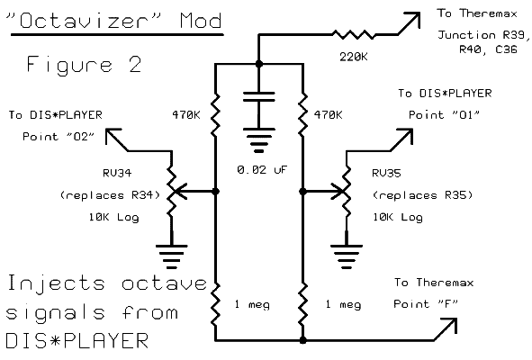
- Injecting a sample of the octave dividers from
DIS*PLAYER works
great, and gives a really cool effects option. A neat thing about this
is that the timbre pot affects the timbre of the subharmonic octaves also,
since effectively two separate samples are injected at either end of the
timbre control; one "raw" (square- wave) and one after low-pass
filtration. Wire according to the diagram of Figure 2, below.

- I also didn't care for the heavy high frequency roll-off. There's a
compromise here - if you go too far the other way, you get some pretty
shrill highs. My personal preference was achieved by changing C39 to
.001 µF., and C44 to .002 µF.
- Shielding the "reference" oscillators with small pieces of un-etched
pc board (on both sides of the Theremax board) greatly reduces the
tendency to lock up near zero-beat. Without the shielding, lockup occurs
at around 20-30 Hz. With it, you can get stable frequencies down to
under 10 Hz., with less chatter as the oscillators lock.
Back to Top
More mods, from PAiA
About Dis*Player
Theremin Home
Back to Fred's Freebies
To my music home page
---This page last updated April 18, 2002.


